
Windtracker twin-turbine system

a twin-turbine system and wind tracker technology, applied in the direction of electric generator control, renewable energy generation, greenhouse gas reduction, etc., can solve the problems of inability to operate economically and inability to achieve the independence of the wind direction

Active Publication Date: 2014-02-27
DIRECTTECH GLOBAL GMBH
View PDF16 Cites 4 Cited by
  • Summary
  • Abstract
  • Description
  • Claims
  • Application Information

AI Technical Summary

Benefits of technology

The invention is a turbine that uses golf balls to generate power. It has small depressions on its surface called dimples that help improve its adhesion and increase turbulence. This increases the lifting force, allowing the ball to be lifted and fly more easily. The turbine also uses a ring generator for power generation and can operate at low wind speeds. It can also be used in circulating winds, where wind speed is greater at a low height. Overall, the invention provides a cost-effective and efficient way to generate power.

Problems solved by technology

However, this has the drawback that, because of the deflector plate, independence from the wind direction is no longer achieved.
In this case, economical operation is not possible.

Method used


Image

  • Windtracker twin-turbine system
  • Windtracker twin-turbine system
  • Windtracker twin-turbine system

Examples


embodiments

[0022]In the following, a plurality of embodiments of the invention are described in greater detail by way of drawings. Like reference numerals have the same significance in all of the drawings and are therefore only explained once.

[0023]In the drawings:

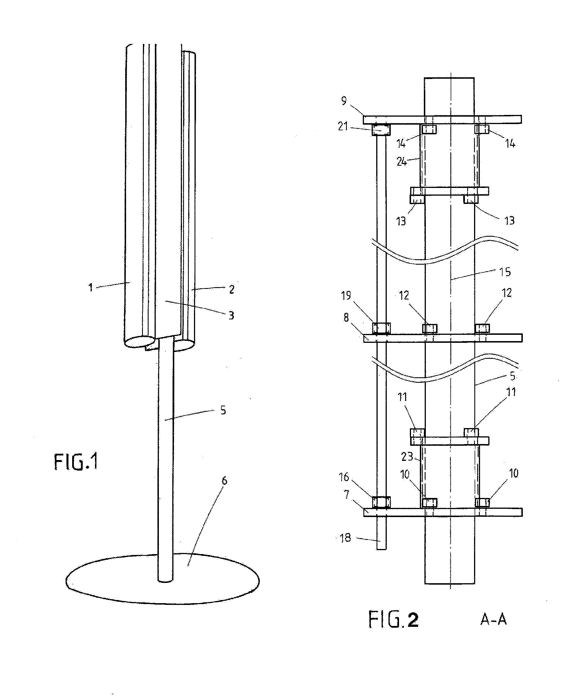
[0024]FIG. 1 is a perspective drawing of the wind generator according to the invention comprising two radial turbines,

[0025]FIG. 2 shows the constructional details of an embodiment as a tubular mast mounting system in a view from the side in accordance with A-A in FIG. 3,

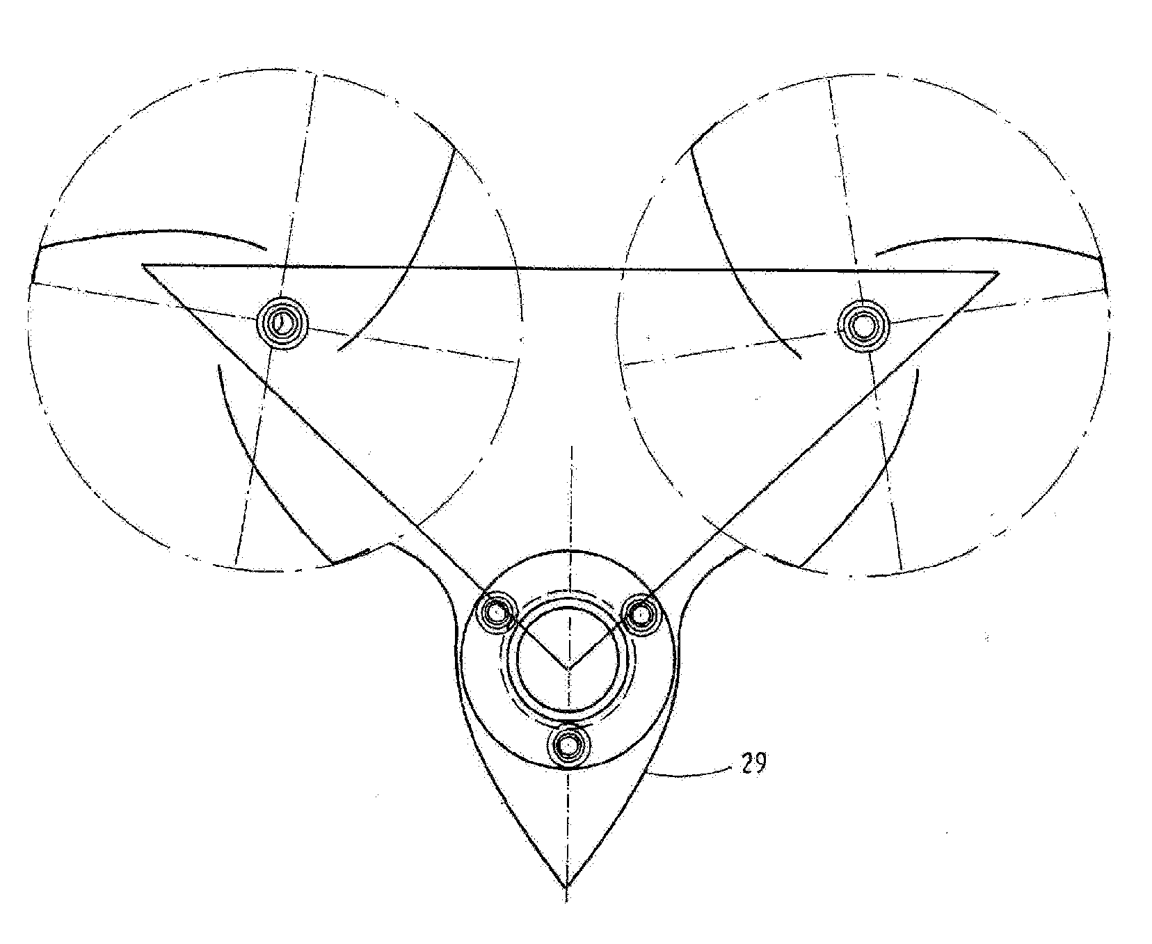
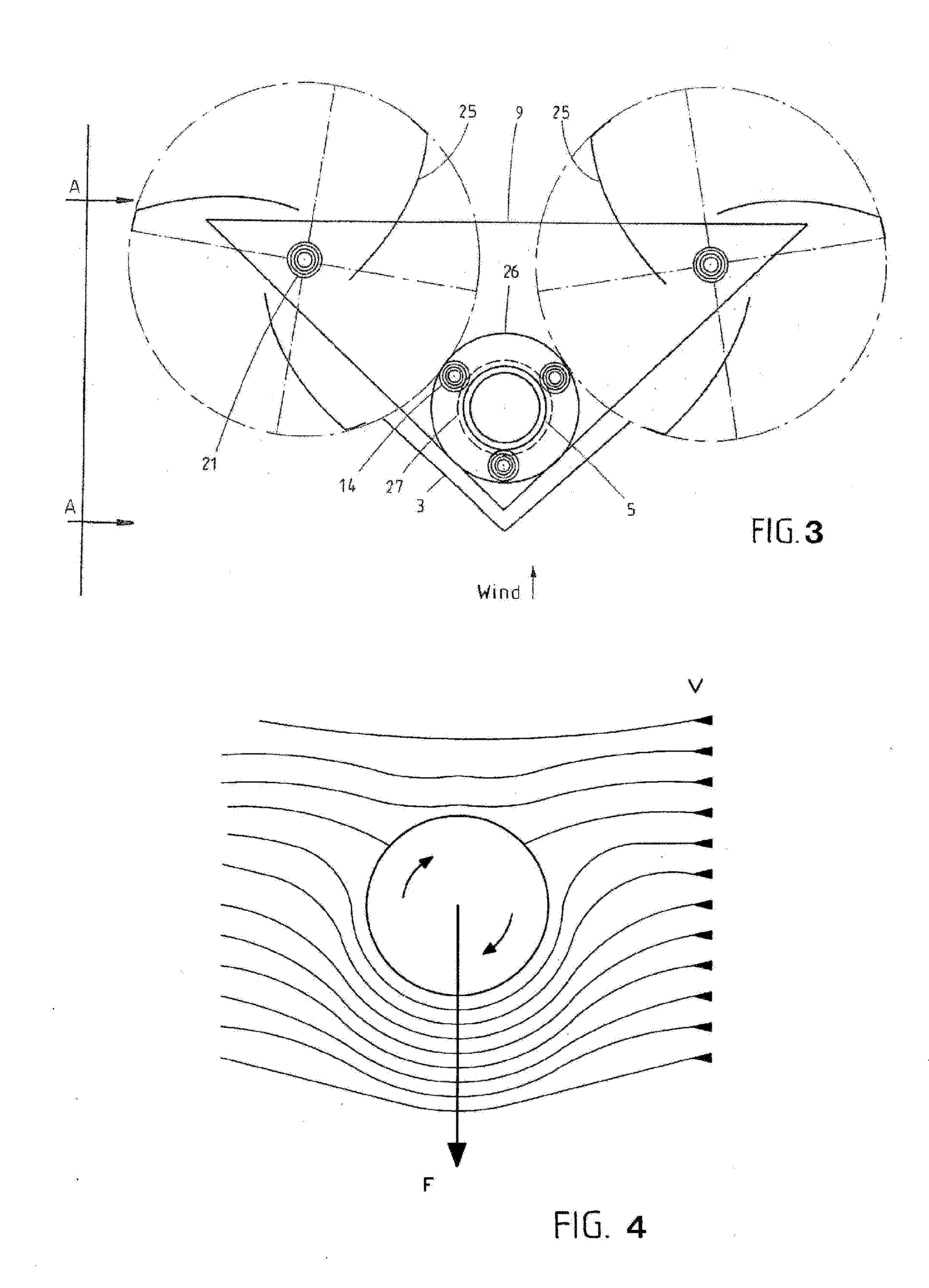
[0026]FIG. 3 is a plan view of the wind generator,

[0027]FIG. 4 shows a rotating roller with surrounding fluid,

[0028]FIG. 5 shows the thread test,

[0029]FIGS. 6 to 8 show further variants with modified wind splitters 29 and additional concentration plates 30,

[0030]FIG. 9 shows torque vs. rotational speed characteristics,

[0031]FIG. 10 shows further characteristics,

[0032]FIG. 11 is a view comprising two additional deflector plates 38, 39,

[0033]FIG. 12 and FIG. 13a are vi...


PUM


Abstract

A turbine system for wind and / or water power is characterized in that two radial turbines (1, 2) aligned next to each other and in parallel are arranged having a vertical axis of rotation, said radial turbines being connected to each other and being pivotable about a pivot axis (3) parallel to the turbine axes (18), wherein the pivot axis and a V-shaped wind distributor (3) are located outside the connecting line between the turbine axes and both on the same side of the connecting line.

Description

[0001]The invention relates to a turbine system comprising two radial turbines in accordance with the preamble of claim 1.PRIOR ART[0002]By comparison with the known three-blade wind generators having a horizontal axis of rotation and aircraft-type blades, a radial turbine has the major advantage of operating independently of the direction of the incident wind. Thus, the radial turbine having a vertical axis of rotation does not have to be turned to the wind.[0003]In a particularly economical embodiment, the radial turbine is provided with deflector plates, which collect the wind energy and deflect it onto the blades of the radial turbine in a concentrated form. However, this has the drawback that, because of the deflector plate, independence from the wind direction is no longer achieved. The radial turbine comprising a deflector plate therefore has to be tracked to the wind.[0004]An arrangement according to the international patent application WO 2011 / 059760 A2 [U.S. Pat. No. 8,167...

Claims


Application Information

Patent Timeline
Patent Type & Authority Applications(United States)
IPC IPC(8): H02K7/18
CPCH02K7/1823F03D3/005F05B2210/16F05B2240/213F05B2240/217F05B2240/40Y02B10/30Y02E10/74F03D3/062F03D3/02F03D3/04F03D3/06
Inventor STEEL, DENNIS PATRICK
Owner DIRECTTECH GLOBAL GMBH
Learn More