Flexible linkage camera system and method for visual inspection of off line industrial gas turbines and other power generation machinery

a gas turbine and flexible technology, applied in the field of optical camera systems for non-destructive internal inspection of power generation machinery, can solve the problems of difficult positioning of inspection apparatuses, narrow confines of passages surrounding stationary vanes, and inability to move too easily or limp to prevent controlled positioning within passages, etc., to achieve the effect of resuming power generation more quickly

Active Publication Date: 2014-02-27
SIEMENS ENERGY INC
View PDF3 Cites 29 Cited by
  • Summary
  • Abstract
  • Description
  • Claims
  • Application Information

AI Technical Summary

Benefits of technology

[0012]Accordingly, potential objects of the invention, jointly or severally among others, are to create optical camera inspection systems and methods for capturing images of internal areas of interest within power generation machinery, (including by way of non-limiting example steam or gas turbines and generators) that are selectively insertable through machinery access points and deliverable through internal passages with minimal (preferably no) dismantling of the machinery, to obtain inspection access of areas of interest. With such inspection systems and methods the inspected power generation machine can be brought back on line for resuming power generation more quickly during maintenance cycle inspection, without spending time and effort to dismantle and reassemble the machinery.
[0013]Other potential objects of the invention, jointly or severally among others, are to create optical camera inspection systems and methods for capturing images of internal areas of interest within power generation machinery consistently and repetitively within an individual machine's inspection cycle with minimized risk of damage to machine internal components, high image quality, and quicker inspection cycling time than is attained by the known manual inspection apparatus and methods.
[0014]These and other objects, among others, are achieved by embodiments of the invention. The optical camera inspection systems and methods of the invention utilize cable carriers to insert, deliver and position inspection camera heads that house inspection cameras through power machinery internal passages with minimal (and often no) dismantling of the machinery, to obtain inspection access of areas of interest. The cable carriers have individual chain links that restrict flexure motion to bi-directional pivotal planar motion relative to each link's respective ink centerline. Other embodiments include a connector block coupled between the cable carrier distal end and the camera head. The connector block has a pivot axis coupled to the camera head for swinging the camera head along a camera head range of motion path that intersects the cable carrier flexure motion plane. In other embodiments a camera head swing motion drive system is coupled to the camera head, for selectively positioning the camera head along the camera head range of motion path. The drive system has opposed first and second biasing elements respectively coupled to the camera head laterally in opposed offset positions relative to the connector block pivot axis. When operating the drive system, biasing the first biasing element swings the camera head in a first direction and biasing the second biasing element swings the camera head in a second direction. With such inspection systems and methods the inspected power generation machine is brought back on line for resuming power generation more quickly during maintenance cycle inspection, without spending time and effort to dismantle and reassemble the machinery as required for known inspection systems. The camera inspection systems and methods of the invention embodiments are especially suitable for inspecting stationary vane rows within compressor and turbine sections of industrial gas turbines, as well as other hard-to-reach areas of interest within power machinery. These inspection system and inspection method embodiments facilitate capturing images of internal areas of interest within power generation machinery consistently and repetitively within an individual machine's inspection cycle with minimized risk of damage to machine internal components, high image quality, and quicker inspection cycling time than is attained by the known manual inspection apparatus and methods.

Problems solved by technology

The narrow confines of passages surrounding stationary vanes often will not facilitate passage of traditional inspection scope systems.
Inspection apparatus positioning is challenging due to the complex, often tortuous manipulation paths between components in a gas turbine.
The inspection scope camera delivery system must be sufficiently flexible to insert through tight confined passages, yet not too flexible or limp to prevent controlled positioning within the passages.

Method used


Image

  • Flexible linkage camera system and method for visual inspection of off line industrial gas turbines and other power generation machinery
  • Flexible linkage camera system and method for visual inspection of off line industrial gas turbines and other power generation machinery
  • Flexible linkage camera system and method for visual inspection of off line industrial gas turbines and other power generation machinery

Examples


Embodiment Construction

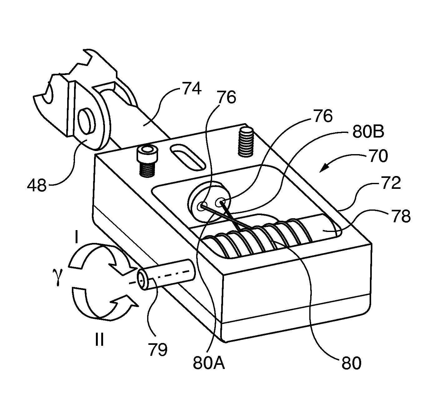
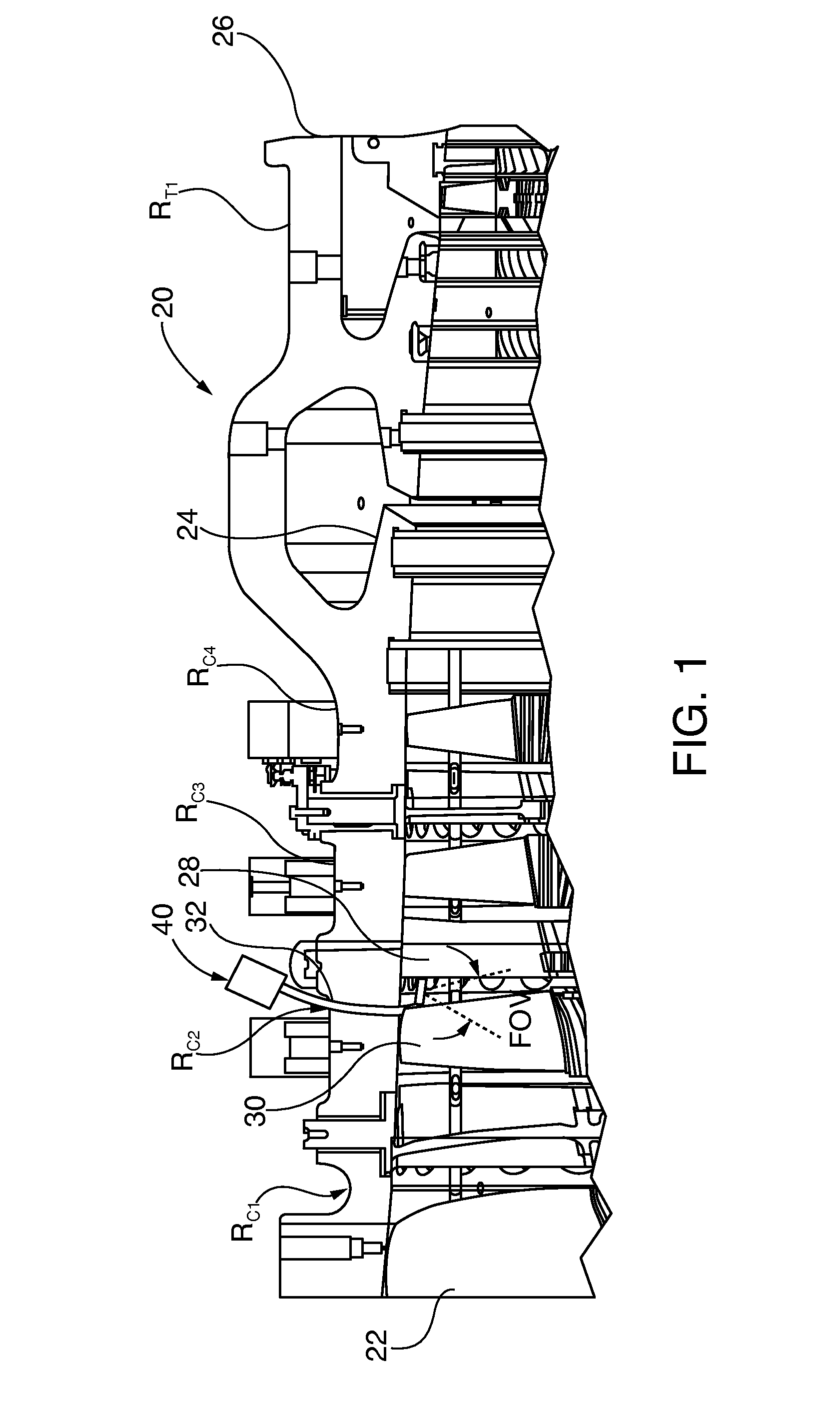
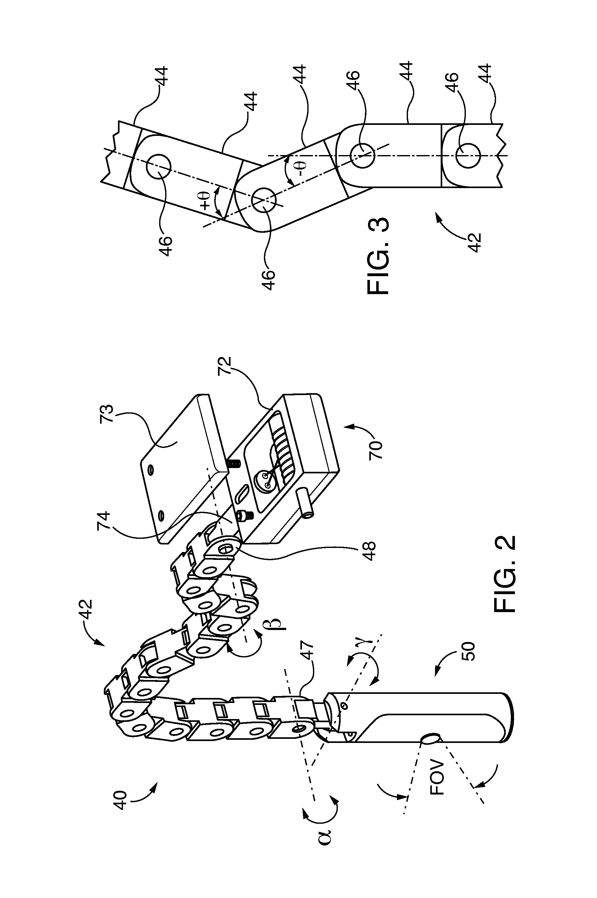
[0030]After considering the following description, those skilled in the art will clearly realize that the teachings of the present invention can be readily utilized for inspection of internal components of power generation machinery, such as generators, gas or steam turbines with a camera inspection system that is inserted and positioned within the machine, for example through a gas turbine compressor section to capture images of a row of stationary vanes. The camera, mounted on a camera head, is inserted and positioned within the machinery by an elongated cable carrier that has restricted cable flexure along a two-dimensional carrier cable flexure motion plane. The camera head that retains the camera is coupled to a distal end of the cable carrier. Embodiments also include a connector block coupled between the cable carrier distal end and the camera head. The connector block has a pivot axis coupled to the camera head for swinging the camera head along a camera head range of motion...


PUM


Abstract

Internal components of power generation machinery, including for example gas or steam industrial turbines as well as generators, are inspected a camera inspection system that is inserted and positioned within the machinery by an elongated cable carrier that has restricted cable flexure along a two-dimensional carrier cable flexure motion plane. A camera head that retains the camera is coupled to a distal end of the cable carrier. Embodiments also include a connector block coupled between the cable carrier distal end and the camera head. The connector block has a pivot axis coupled to the camera head for swinging the camera head along a camera head range of motion path that intersects the cable carrier flexure motion plane. Embodiments include a camera head swing motion drive system for selectively positioning the camera head along the camera head range of motion path.

Description

REFERENCE TO CO-PENDING APPLICATIONS[0001]This application claims the benefit of co-pending United States patent application entitled “System And Method For Visual Inspection And 3D White Light Scanning Of Off-Line Industrial Gas Turbines And Other Power Generation Machinery”, filed on the same date herewith and assigned Ser. No. (13 / 972,000), Siemens Docket Number 2013P09381US (Siemens 185) that in turn claims the benefit of copending United States provisional patent application entitled “Vision Scope 3D Scanner Tip for Visual Inspection and Measurement” filed Aug. 23, 2012 and assigned Ser. No. 61 / 692,409. All of said cited co-pending cited applications are incorporated by reference herein.BACKGROUND OF THE DISCLOSURE[0002]1. Field of the Invention[0003]The invention relates to optical camera systems for nondestructive internal inspection of power generation machinery, including by way of non-limiting example industrial gas and steam turbines as well as generators. More particular...

Claims


Application Information

Patent Timeline
Patent Type & Authority Applications(United States)
IPC IPC(8): H04N7/18
CPCH04N7/185G02B23/2492B25J9/065F01D21/003F05D2270/8041F01D25/285G01N21/8803G01N21/8806
Inventor HATCHER, JR., CLIFFORDHATLEY, RICHARD
Owner SIEMENS ENERGY INC
Why Eureka
Try Eureka