A new type of rotating plate resistance type high-efficiency power generation device

A power generation device, resistance-type technology, applied in the field of new rotating plate resistance-type high-efficiency power generation devices, can solve the problems of not maximizing the force difference, different forces on the blades on both sides of the central shaft, and poor power generation effect, etc., to achieve It has a wide range of applications and the effect of improving the utilization rate of wind energy

Active Publication Date: 2019-03-12
傅强 +1
View PDF5 Cites 0 Cited by
  • Summary
  • Abstract
  • Description
  • Claims
  • Application Information

AI Technical Summary

Problems solved by technology

[0004] The 3-blade wind turbine consists of 3 triangular slender blades as the force-receiving surface of the wind energy. Since the blades have an included angle with the direction of the wind, the blades are driven by the kinetic energy of the wind to perform axial rotation (but the direction of rotation is different from that of the wind). The direction of the wind is different) to drive the generator to generate electricity, but the actual conversion efficiency of wind energy into electricity is not as high as the theory claims, and the overall conversion rate is low, especially at low wind speeds. Only when the wind speed reaches 2-3 meters per second can electricity be generated, and the overall utilization rate of wind energy is only about 20%.
③Some large and medium-sized 3-blade wind turbine blades are designed to have a convex and concave wing cross-section shape, which is the so-called lift-type blade. It is hoped to increase the speed and then improve the power generation efficiency, but the actual improvement effect is limited
[0005] When the wind blows over the Darrieux-type H-type, Φ-type, and S-type vertical axis wind turbines, the two sides of the central axis of this type of wind turbine will be stressed at the same time. However, due to the different shapes of the blades on both sides, the two sides of the central axis The force on the side blades is different, and the difference in force causes the impeller to rotate towards the side where the force is greater. Although this type of wind turbine has been designed with different blade shapes on both sides of the central axis to increase the difference in force, However, the force difference on both sides is still small, and the force difference has not been maximized, that is, a considerable part of the wind energy blown to the wind turbine is canceled due to the structure of the wind turbine and cannot be used to generate electricity. The reason why this type of wind turbine is difficult to start rotating to generate electricity under low wind speed conditions or the power generation effect is poor, and it is easy to be damaged under strong wind

Method used


Image

  • A new type of rotating plate resistance type high-efficiency power generation device
  • A new type of rotating plate resistance type high-efficiency power generation device
  • A new type of rotating plate resistance type high-efficiency power generation device

Examples


Embodiment 1

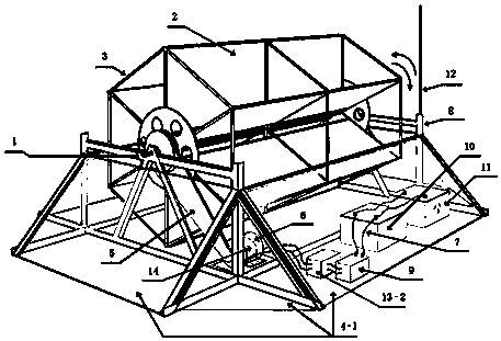
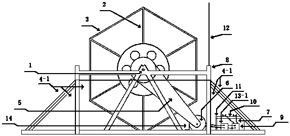
[0057] Embodiment 1: When used for wind power generation, the central axis is placed horizontally on the ground, and the whole machine support is placed under the central axis. The whole machine has a stable structure like a pyramid, and the drainage plate (4-1) is placed under the central axis. The whole machine support One or more sides (the diversion plate plays the role of blocking the wind from blowing to the blades below the central axis and allowing the wind to only blow to the blades above the central axis, and also slows down the impact of the wind on the whole machine and guides part of the wind to turn blowing to the blades rotating to a position above the central axis). When the wind blows, the blades below the central axis of the machine are covered by the deflector plate, so the force is almost zero, and only the blades that turn to the part above the central axis receive the impact of wind energy, generate rotating mechanical motion, and drive power generation th...

Embodiment 2

[0058] Embodiment two: the wind power generator of embodiment one form, change its generating unit into alternator: when the electric energy output unit of connection comprises AC-DC converter (13-2), output controller, cable, when storage battery , the generated power can be used by electrical appliances using direct current. When the connected electric energy output unit includes an AC-DC converter (13-2), an output controller, a cable, a storage battery, and an inverter, the generated power can be used for alternating current The use of electrical appliances (see the attached instructions for the form) figure 2 ); can also be incorporated into the external network.

Embodiment 3

[0059] Embodiment 3: Turn the machine in the form of Embodiment 1 upside down, put the part below the central axis into the water, connect the bracket of the whole machine with the embankment or bridge and fix it, then it can be used as a hydroelectric generator (the lightning rod needs to be changed to become a whole machine highest point)

[0060] (see the attached manual for the form) Figure 9 ).


PUM


Abstract

The utility model relates to a change the high -efficient power generation facility of board -like resistance type, the principle is that the kinetic energy of wind or rivers acts on machinery, carries out turning into behind the mechanical motion electric energy. The essential element: the impeller, a plurality of blades that contain the axis and arrange around this axial heart leave the space between and the axis, and they become the column body by the leg joint, and axis one side blade is rotatory under the kinetic energy impact of wind or rivers, electrical cell is with speed change gear and leg joint, speed change gear is connected with axis and electrical cell, the drainage plate for straight plate -type or cambered surface shape, plays wind direction and bridging effect with the leg joint, and the blade that shelters from axis one side makes its not atress and opposite side blade atress, output controller, AC DC converter, inverter. The electric power storage storage battery, the lightning rod, positive negative pole commutator, complete machine supports etc. Still can become scene ability or water light energy electricity generation all -in -one when making the drainage plate with solar cell panel.

Description

technical field [0001] The invention relates to a new type of rotating plate resistance type high-efficiency power generation device, which is a device that converts wind energy (that is, the kinetic energy of air flow) or water flow energy into mechanical energy and then into electrical energy, and is a device with relatively high conversion efficiency. Power Equipment. The diversion plate of the present invention can be composed of solar panels, and then the present invention becomes an integrated device for wind and solar power generation or an integrated device for hydro-solar power generation. The present invention can be used in a variety of ways and in different occasions, and is suitable for places rich in wind energy and water energy resources such as roofs, sides of buildings, balconies, open spaces in residential quarters, grasslands, Gobi, mountains, hills, deserts, rivers, etc., off-grid It can be connected to the grid for power generation, and it is an ideal pow...

Claims


Application Information

Patent Timeline
Patent Type & Authority Patents(China)
IPC IPC(8): F03D9/11F03B13/00
CPCY02E10/72Y02E70/30Y02P90/50
Inventor 傅强王芸惠
Owner 傅强
Why Eureka
Try Eureka