
Extreme load control

a load control and load technology, applied in the direction of motors, engine control parameters, comparison table algorithms, etc., can solve the problems of increasing the risk of continuous delivery of power from the turbine, and the rate of wear or accumulation of damage, so as to achieve the effect of reducing the risk of exceeding the maximum load

Active Publication Date: 2020-09-01
VESTAS WIND SYST AS
View PDF16 Cites 0 Cited by
  • Summary
  • Abstract
  • Description
  • Claims
  • Application Information

AI Technical Summary

Benefits of technology

This patent aims to improve wind turbine control systems so that they can produce more power than their rated capacity without causing damage to the turbine. This is done by controlling parameters such as rotor speed, torque, or generator current demand. Over-rating allows for greater power extraction, particularly when external conditions are favorable.

Problems solved by technology

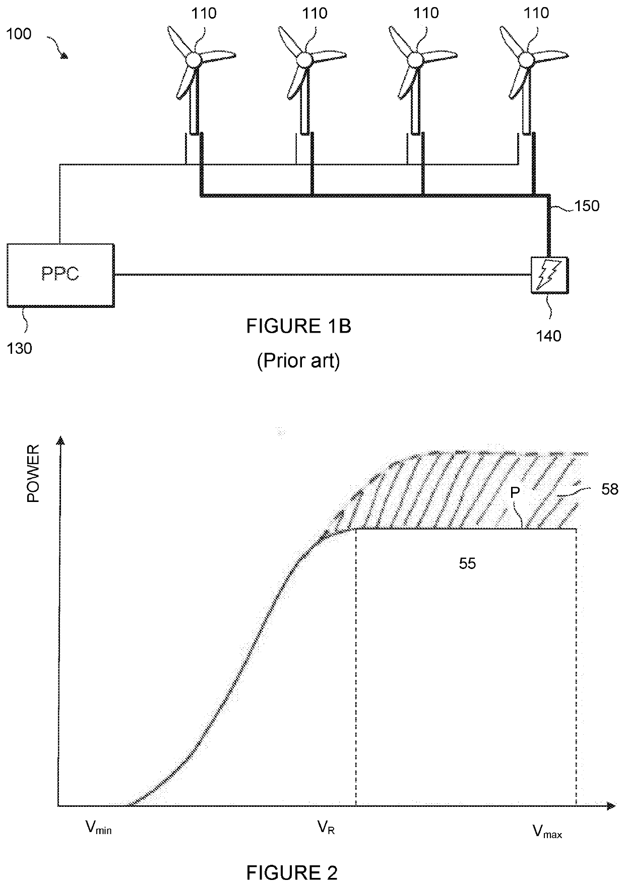
Further indicated on the graph of FIG. 2 is a maximum wind speed Vmax above which continued deliverance of power from the turbine may become dangerous, in particular due to the loads experienced by the turbine components.
In practice, however, that total rated power may rarely be reached.
This may be for a range of reasons, such as less-than-ideal wind conditions at the specific sites of some of the individual turbines, or simply because one or more turbines may be non-operational (for example, undergoing maintenance) at any given time.
The rate of wear, or accumulation of damage, tends to increase as generated power increases.
Wind conditions also affect rate of accumulation of damage.
For some mechanical components, operation in very high turbulence causes a rate of accumulation of fatigue damage that is many times higher than in normal turbulence.
For some electrical components, operation at very high local temperatures, which may be caused by high ambient temperatures, causes a rate of accumulation of fatigue damage, such as insulation breakdown rate, that is many times higher than in normal temperatures.
An increase in speed demand, torque demand and / or generator current demand increases additional power produced by over-rating, whereas a decrease in speed, torque and / or generator current demand decreases additional power produced by over-rating.
Over-rating causes higher wear or fatigue on components of the wind turbine, which may result in early failure of one or more components and require shut down of the turbine for maintenance.
Fatigue loading encompasses broadly those stresses that are, to a greater or lesser degree, constant and continuous whenever a wind turbine is in operation and which can cause turbine components to sustain material wear or degradation over time.
Conversely, extreme loads, which are of interest here, typically arise due to one-time or infrequent events or weather conditions that may cause immediate and / or serious damage to a wind turbine or to its components.
Thus, the design of a wind turbine is subject to a considerable number of assumptions about the manner in which the machine will operate once in place and the loads it will be subjected to as a result.
However, a problem which, to the inventor's knowledge, remains to be addressed is the manner in which over-rating is prevented outright where an increase in power output could cause the ultimate design loads on one or more components to be exceeded.
Further, even where over-rating is possible, it may only be possible to a very limited extent; that is, for only a relatively small increase in power output.
In those cases, the benefits from over-rating are significantly inferior to the benefits that could be gained were all spare fatigue capacity to be utilised.
In addition, increasing numbers of modern turbine designs are limited by operational extreme loads; that is, extreme load cases that arise at wind speeds in the (operational) range of 4 to 25 ms−1, as distinct from non-operational load cases that arise at wind speeds of over 40 ms−1.

Method used


Image

  • Extreme load control
  • Extreme load control
  • Extreme load control

Examples


Embodiment Construction

[0041]A common approach to wind turbine design and, more particularly, to engineering a turbine to withstand the various loads it is expected to experience, is to consider in turn the various states or situations in which a turbine may be at any given time. Each of these so-called ‘load cases’ represents a design situation characterised by a set of loads and other conditions to be taken into account. The design load cases set out in IEC 64100-1 are given in Table 1 below. In the table, the letter ‘U’ in the penultimate column designates a load case analysed as an ultimate load case, and ‘F’ a fatigue load case.

[0042]As mentioned above, fatigue load cases are not the direct subject of this invention. The ultimate load cases can, for the purposes of the present discussion, be conveniently divided into three main classes. A first class includes non-operational load cases, such as the extreme (or 50-year) wind speed model (EWM) considered within the ‘Parked’ situation. These load cases ...


PUM


Abstract

Methods for calculating a maximum safe over-rated power demand for a wind turbine operating in non-standard conditions include the steps of determining a value indicative of a risk of exceeding an ultimate design load during operation in a standard operating condition, and establishing a maximum over-rated power demand corresponding to a maximum power that the turbine may produce under the non-standard operating condition without incurring an increased risk of exceeding the ultimate design load, with respect to operation in the standard condition. A method of over-rating a wind turbine, a wind turbine controller, a wind turbine and a wind power plant are also claimed.

Description

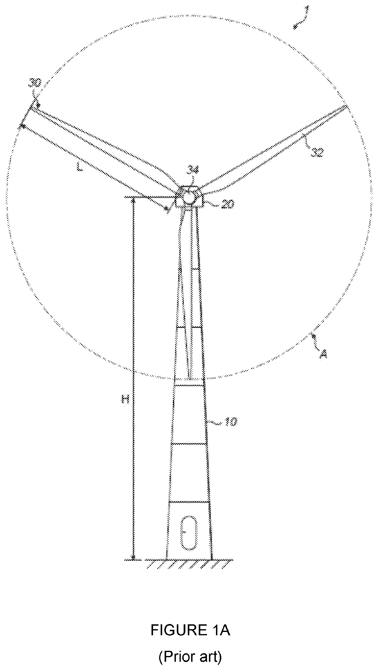
[0001]The present invention relates to control methods and systems for a wind turbine. In particular, the invention provides methods and systems for controlling the extreme loads experienced by a turbine during over-rated operation.[0002]FIG. 1A illustrates a large conventional wind turbine 1, as known in the art, comprising a tower 10 and a wind turbine nacelle 20 positioned on top of the tower 10. The wind turbine rotor 30 comprises three wind turbine blades 32 each having a length L. The wind turbine rotor 30 could comprise any other number of blades 32, such as one, two, four, five or more. The blades 32 are mounted on a hub 34 which is located at a height H above the base of the tower. The hub 34 is connected to the nacelle 20 through a low speed shaft (not shown) extending from the front of the nacelle 20. The low speed shaft drives a gearbox (not shown) which steps up the rotational speed and, in turn, drives an electrical generator within the nacelle 20 for converting the en...

Claims


Application Information

Patent Timeline
Patent Type & Authority Patents(United States)
IPC IPC(8): F03D7/02G05B9/02
CPCG05B9/02F03D7/0288F05B2270/708F05B2270/329F05B2270/321F05B2270/332F05B2270/1033F05B2270/1095Y02E10/72F05B2270/32
Inventor SPRUCE, CHRIS
Owner VESTAS WIND SYST AS
Learn More