
System for establishing and maintaining a clock reference indicating one-way latency in a data network

Active Publication Date: 2014-02-27
ACCEDIAN NETWORKS
View PDF10 Cites 69 Cited by
  • Summary
  • Abstract
  • Description
  • Claims
  • Application Information

AI Technical Summary

Benefits of technology

The patent describes a new technology that enables highly accurate measurements of latency in a network where resistance to real-time synchronization is present. This technology can measure the time it takes for a message to pass through a network with high precision, even when there is no global clock synchronization available. It can also provide individual measurements for each packet and make high-precision latency measurements of packets traveling between two nodes over time. This technology ensures accuracy in virtual clock synchronization between source and destination, which avoids the need for a lengthy synchronization phase before each measurement.

Problems solved by technology

Using GPS for synchronizing has several drawbacks:the synchronization of several devices, each of which is equipped with a GPS receiver, can be expensivethe GPS antenna has to be located within a specific distance from the receiver, limiting the positioning of monitoring devices
This is the cheapest synchronization technique, but it does not provide as accurate results as GPS does; the accuracy depends on the characteristics of the paths followed by the NTP synchronization messages and on the distance between the NTP server and the source and destination that must be synchronized.

Method used


Image

  • System for establishing and maintaining a clock reference indicating one-way latency in a data network
  • System for establishing and maintaining a clock reference indicating one-way latency in a data network
  • System for establishing and maintaining a clock reference indicating one-way latency in a data network

Examples


Embodiment Construction

[0027]Although the invention will be described in connection with certain preferred embodiments, it will be understood that the invention is not limited to those particular embodiments. On the contrary, the invention is intended to cover all alternatives, modifications, and equivalent arrangements as may be included within the spirit and scope of the invention as defined by the appended claims.

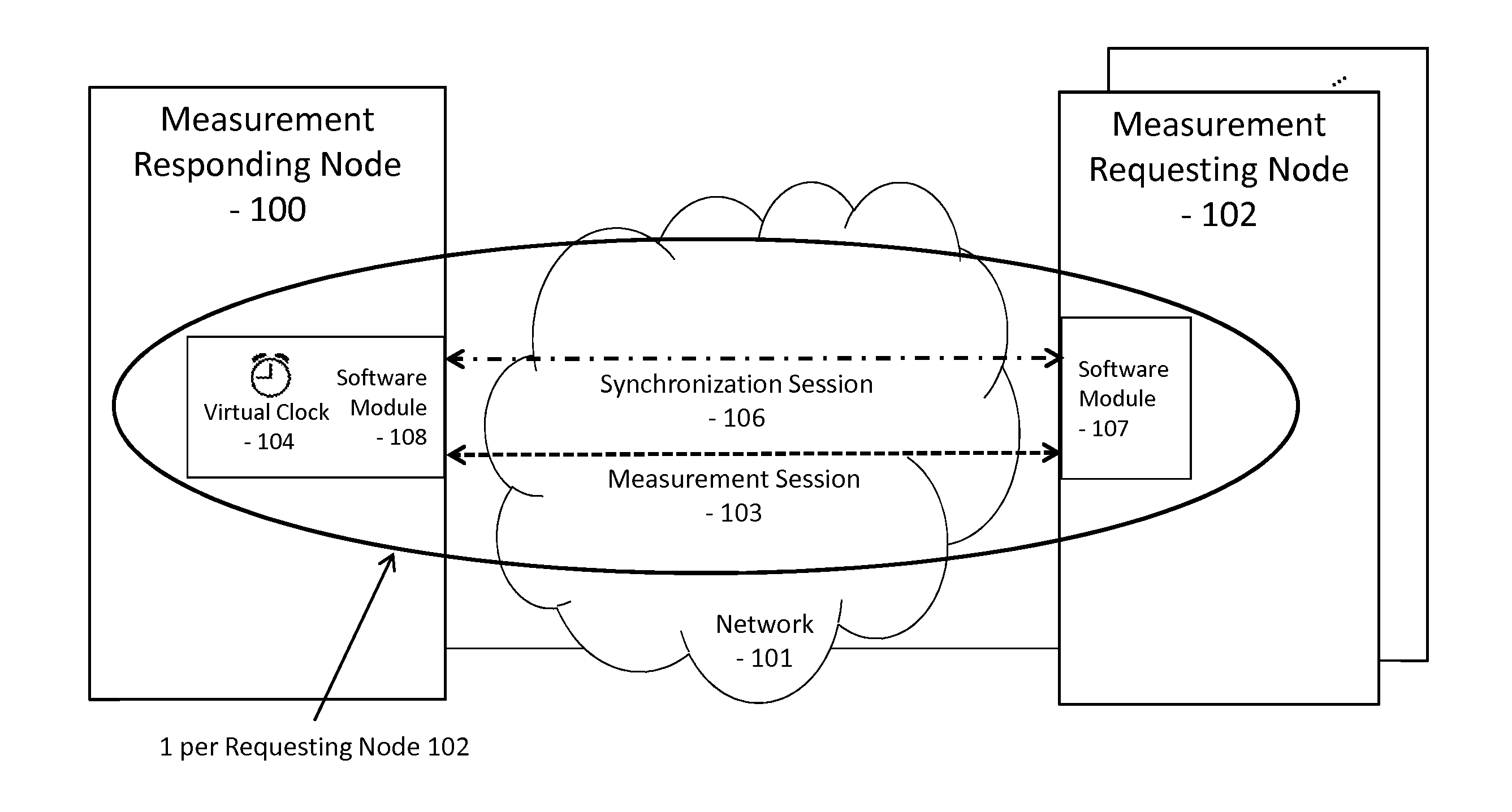
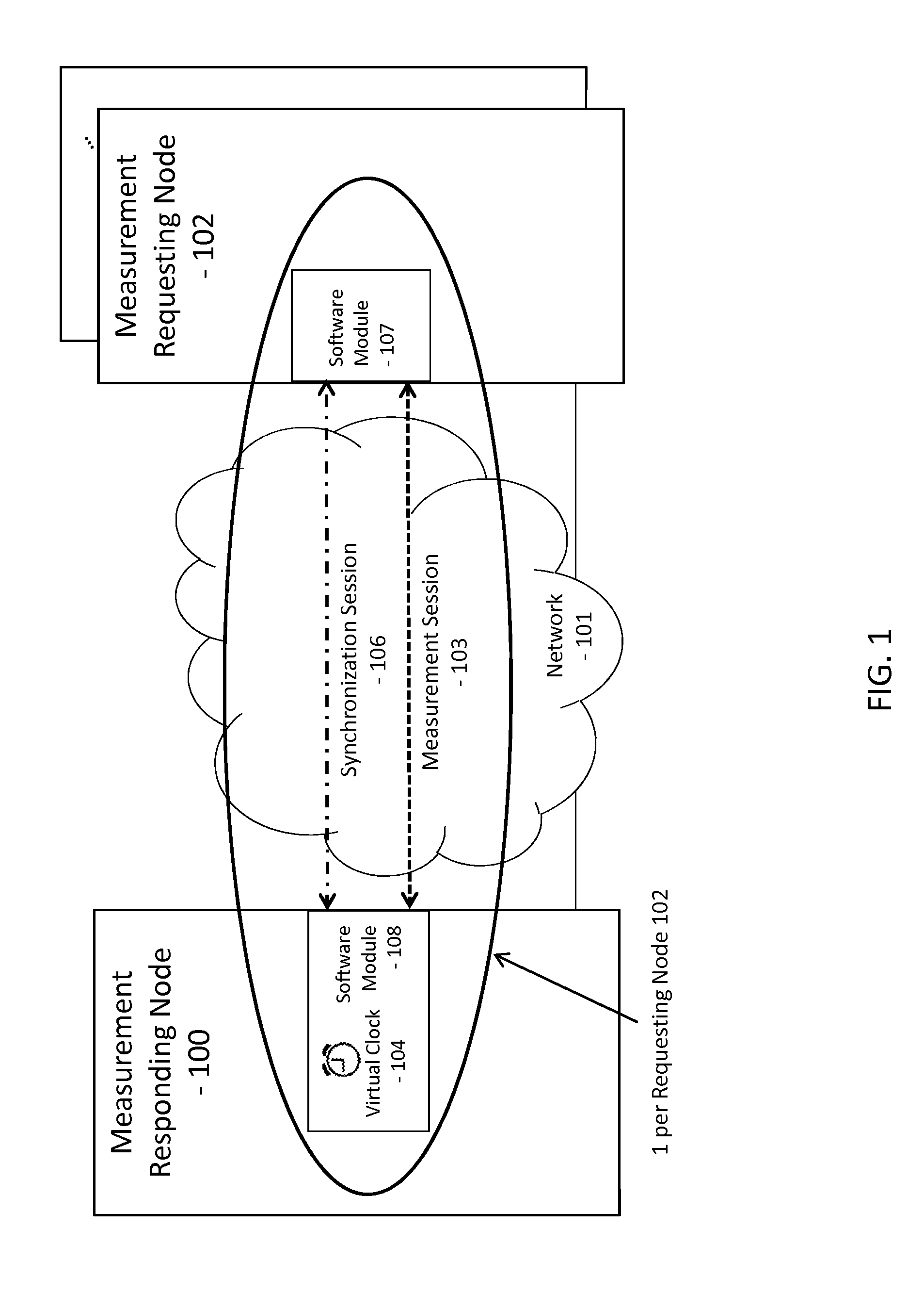
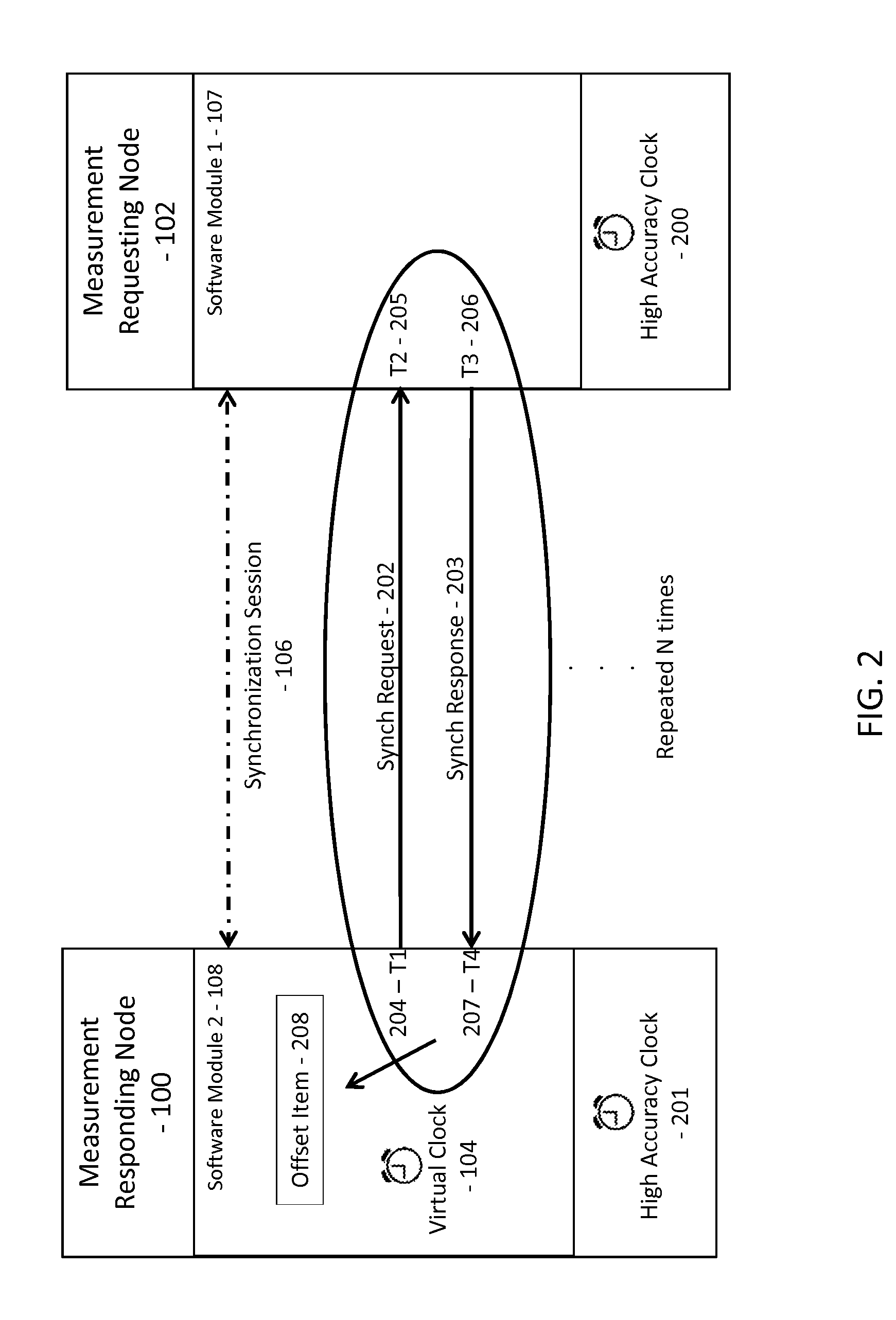
[0028]A method for indicating one-way latency in a data network, with continuous clock synchronization between a first node and a second node is disclosed. The method comprises the exchange of clock synchronization information between a pair of network nodes via a synchronization session. This synchronization session sends synchronization messages at regular intervals and is separate from other management, measurement or user traffic. Synchronization messages do not need to use the same path as other traffic between the pair of nodes. The network node is equipped with a network interface card ...


PUM


Abstract

A method for indicating one-way latency in a data network, with continuous clock synchronization, between first and second node having clocks that are not synchronized with each other includes a continuous synchronisation session and a measurement session. The method repetitively sends predetermined synchronization messages from the first node to the second node and from the second node to the first node, calculates a round trip time for each message at the first node, updates a synchronization point if the calculated round trip time is smaller than a previously calculated round trip time, stores the updated synchronization points of a synchronization window, and calculates a virtual clock from the updated synchronization points of the synchronization window. The measurement session collects multiple measurements of one-way latency between the first and second nodes using the virtual clock, and generates a latency profile by interpolating the multiple measurements.

Description

FIELD OF THE INVENTION[0001]A method for indicating one-way latency in a data network.BACKGROUND OF THE INVENTION[0002]Latency is a measure of time delay experienced in a system. Network latency in a packet-switched network is measured either one-way (the time from the source sending a packet to the destination receiving it), or two-way (the one-way latency from source to destination plus the one-way latency from the destination back to the source). Where precision is important, one-way latency for a link can be more strictly defined as the time from the start of packet transmission to the start of packet reception.[0003]There are many possible techniques to synchronize time between a source and a destination. It is possible to achieve time synchronization by using synchronized clocks that use Global Positioning System (GPS) technology. GPS considers a satellite environment as reference time for the synchronization of the source and the destination. The synchronization accuracy depe...

Claims


Application Information

Patent Timeline
IPC IPC(8): H04J3/06
CPCH04J3/0658H04J3/0667H04L7/0012H04L43/0858H04L43/0864H04L1/0018H04L69/22
Inventor HANSSON, KJELLHAGSAND, OLOF
Owner ACCEDIAN NETWORKS
Learn More