Object information acquiring apparatus, information processing apparatus and object information acquiring method

a technology of object information and acquisition apparatus, applied in the field of object information acquisition apparatus, information processing apparatus and object information acquisition method, can solve the problems of canceling signal components from a focus point, affecting the accuracy of dcmp methods, and insufficient dcmp methods, etc., to achieve the effect of improving resolution

Active Publication Date: 2014-02-27
CANON KK
View PDF9 Cites 6 Cited by
  • Summary
  • Abstract
  • Description
  • Claims
  • Application Information

AI Technical Summary

Benefits of technology

[0012]Ultrasound wave beamforming by the DCMP method is advantageous in that this method affords significantly enhanced resolution in reconstructed images. As is known, however, the DCMP method is problematic in that signal components from a focus point are cancelled when correlated interference waves, which are correlated with the signal component ar

Problems solved by technology

As is known, however, the DCMP method is problematic in that signal components from a focus point are cancelled when correlated interference waves, which are correlated with the signal component arriving from the focus point, are inputted as noise.
In principle, therefore, noise waves from points other than the focus point are all correlated interference waves, which poses a particularly serious problem.
However, these add

Method used


Image

  • Object information acquiring apparatus, information processing apparatus and object information acquiring method
  • Object information acquiring apparatus, information processing apparatus and object information acquiring method
  • Object information acquiring apparatus, information processing apparatus and object information acquiring method

Examples


example 1

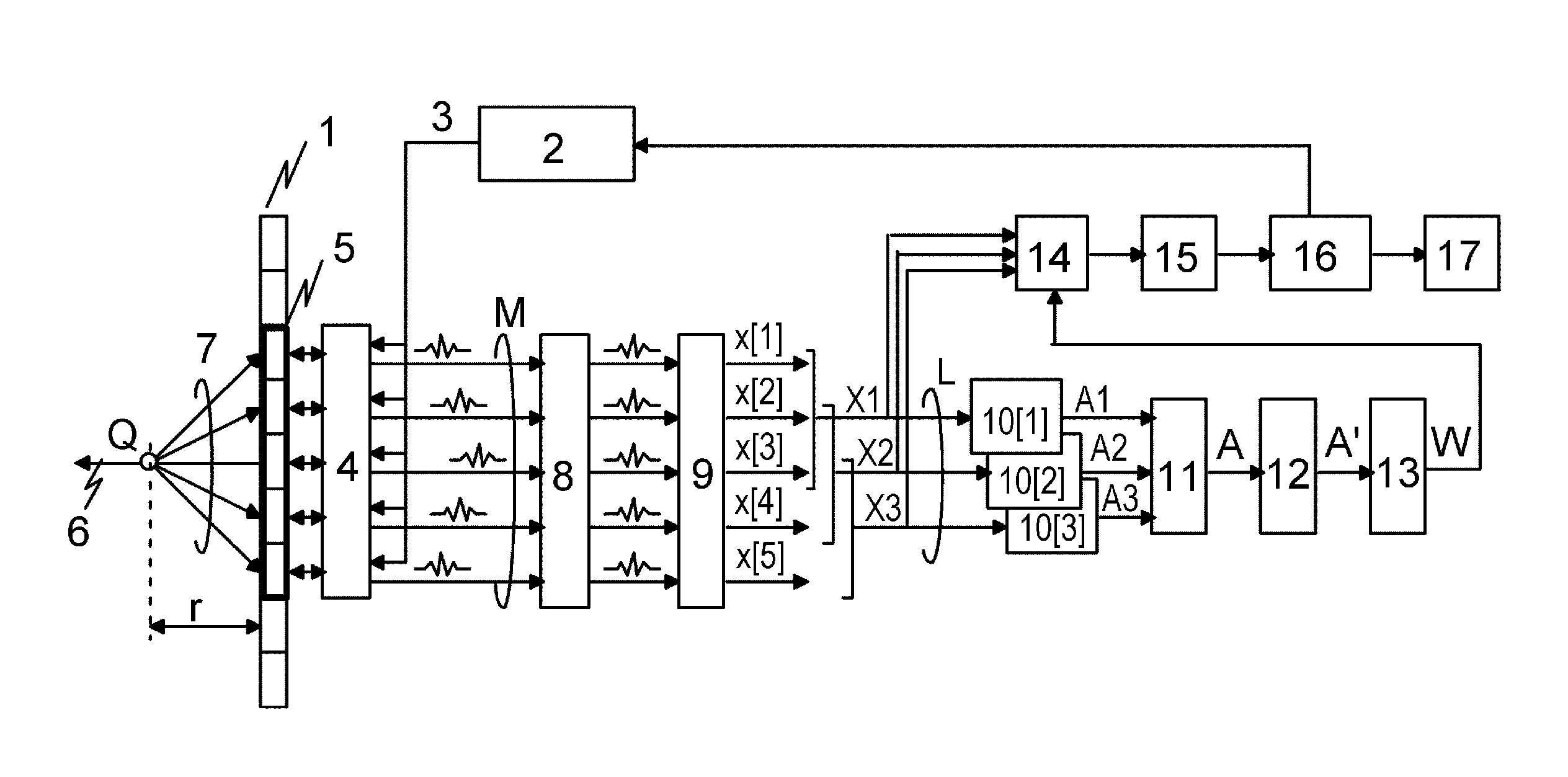
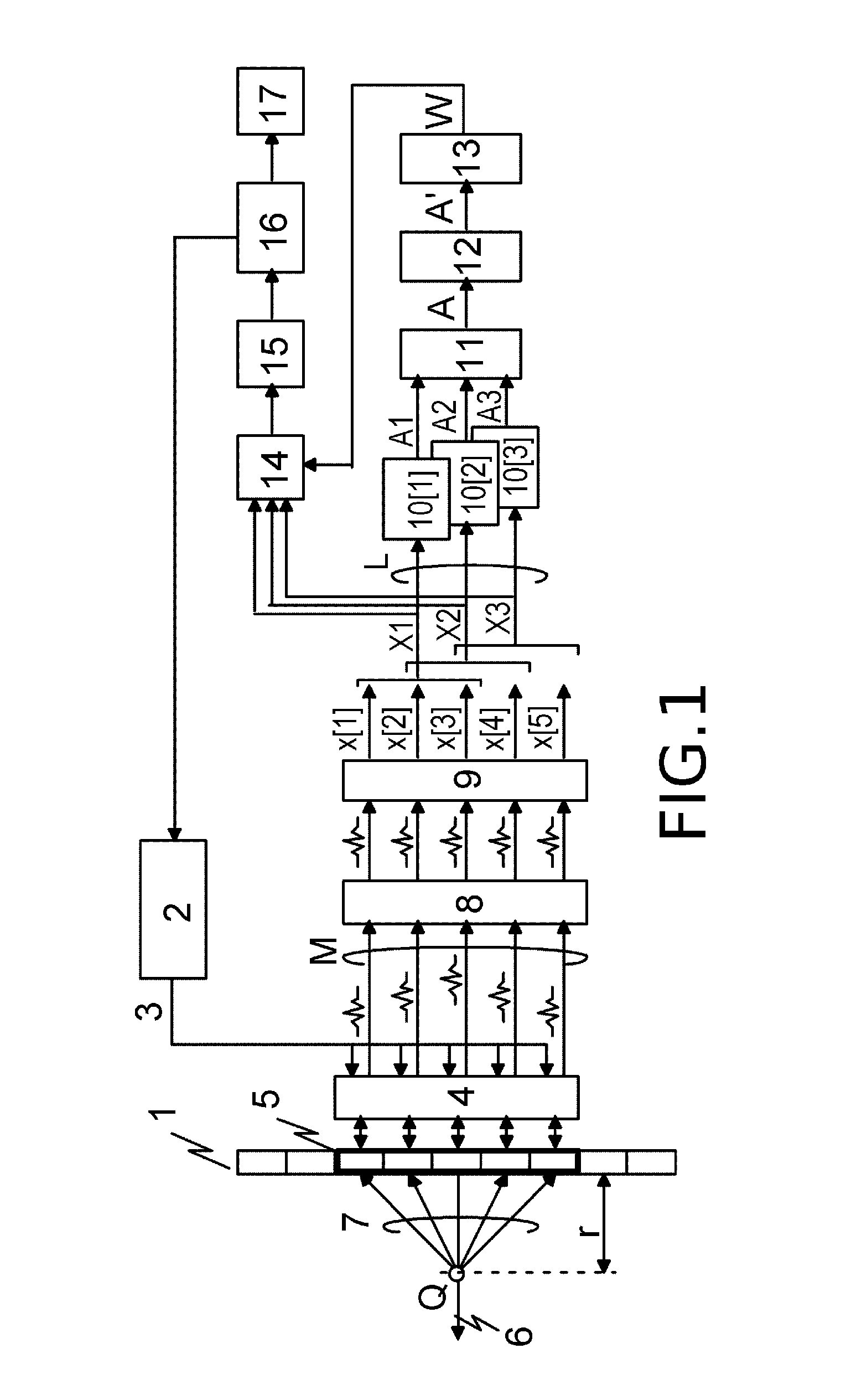
[0072]FIG. 3 is a diagram illustrating a device according to Example 1. Compared with the conventional example of FIG. 1, herein blocks 21 to 25 have been added in Example 1 in place of the output signal calculation circuit 14. The explanation below will focus on this difference.

[0073]A signal intensity calculation circuit 21 calculates, on the basis of Expression (10), an output signal intensity Pw according to the DCMP method, from the modified correlation matrix A′[t] and the optimal weight vector W[t].

[Math 6]

Pw[t]=W[t]HA′[t]W[t]  (10)

[0074]A signal intensity calculation circuit 22 calculates, on the basis of Expression (11) a signal intensity Pc in the direction of arrival of the signals to be received, from the modified correlation matrix A′[t] and the constraint vector C.

[Math 7]

Pc[t]=CHA′[t]C  (11)

[0075]Herein, A′[t] can be approximated by A[t] if the ε parameter is a small positive number, and hence the signal intensity Pc is substantially equal to the average signal intens...

example 2

[0094]FIG. 6 is a diagram illustrating a device according to Example 2. Example 2 corresponds to an example of a simplified version of Example 1. Herein, an output signal Ydas from a direct delay-and-sum beamforming method is subjected to amplitude modulation using the output signal intensity Pw from a DCMP beamforming method.

[0095]A comparison between FIG. 6 of the present example and FIG. 3 of Example 1 shows that the foregoing differ in that the signal intensity calculation circuit 22 and the modulation ratio calculation circuit 23 have been omitted, and the outputted Pw is inputted to the amplitude modulation circuit 25. That is, calculations that utilize the modulation ratio γ are not carried out.

[0096]The amplitude modulation circuit 25 in the present example may perform, for instance, the calculation processing of Expression (18a) or Expression (18b). In these mathematical expressions K is a constant. This way, an output signal that is an intermediate of the two beamforming m...

example 3

[0097]FIG. 7 is a diagram illustrating a device according to Example 3. Example 3 is an example where, as opposed to Example 2, amplitude modulation of the output signal by the DCMP beamforming method is performed using an output intensity signal by the delay-and-sum beamforming method.

[0098]In the figure, the delay-and-sum signal Ydas outputted by the summating circuit 24 is converted to an intensity signal by an absolute-value circuit 31. An output signal Yw by the DCMP method, outputted by the output signal calculation circuit 14, is amplitude-modulated using the intensity signal of the delay-and-sum signal Ydas in the amplitude modulation circuit 32, and the result is inputted to the signal intensity calculation circuit 15.

[0099]For instance, the modulation output signal Y′ outputted by the amplitude modulation circuit 32 is set to be as given by Expression (19a) or Expression (19b). This way, a composite signal can be outputted in which the shortcomings of the two beamforming m...


PUM


Abstract

An object information acquiring apparatus is provided that includes: a plurality of receiving elements which receive an acoustic wave that propagates from an object, and which convert the acoustic wave to a reception signal; an adaptive beamformer that performs adaptive beamforming of adjusting reception directionality in accordance with the reception signal in use of the reception signal; a delay-and-sum beamformer that performs delay-and-sum beamforming having preset directionality in use of the reception signal; an amplitude modulator that uses one output signal of one of the adaptive beamformer and the delay-and-sum beamformer, to perform amplitude modulation on an output signal of the other one of the beamformers; and a generator that, on the basis of a signal outputted by the amplitude modulator, generates image data on the interior of the object.

Description

BACKGROUND OF THE INVENTION[0001]1. Field of the Invention[0002]The present invention relates to an object information acquiring apparatus, an information processing apparatus and an object information acquiring method.[0003]2. Description of the Related Art[0004]Ultrasound imaging devices for imaging of three-dimensional structures in the interior of an object, using ultrasound waves, are widely used as ultrasound diagnosis devices in the medical field.[0005]The performance of ultrasound diagnosis devices improves rapidly year by year in the wake of advances in ultrasound imaging technology. Image reconstruction relying on adaptive signal processing is being researched as one technology aimed at further enhancing that performance. For instance, J. F. Synnevag, et al., “Adaptive Beamforming Applied to Medical Ultrasound Imaging”, IEEE Trans. ULTRASONIC, FERROELECTRICS, AND FREQUENCY CONTROL, VOL. 54, NO. 8, AUGUST 2007, reports an ultrasound wave beamforming technology that relies o...

Claims


Application Information

Patent Timeline
IPC IPC(8): A61B5/00A61B8/00
CPCA61B8/44A61B5/0095A61B8/483G01S7/52047G01S15/8915G01S15/8945G10K11/346
Inventor YODA, HARUO
Owner CANON KK
Why Eureka
Try Eureka