Eureka AIR delivers breakthrough ideas for toughest innovation challenges, trusted by R&D personnel around the world.

Insertion tool for Inter-body Vertebral Prosthetic Device With Self-Deploying Screws

a prosthetic device and self-deploying technology, applied in the field of applicability and methods of spinal disorders using an intervertebral prosthesis, can solve the problems of not always achieving features, co-axial, and unsatisfactory configuration of the opposite deployment of screws/posts, and achieves the effects of convenient use, improved fixation and stabilization, and convenient insertion

Active Publication Date: 2014-02-27
AMICUS DESIGN GRP LLC
View PDF2 Cites 5 Cited by
  • Summary
  • Abstract
  • Description
  • Claims
  • Application Information

AI Technical Summary

Benefits of technology

This patent describes a device for spine surgery that has screws that can be easily inserted into the patient's body without falling out. The screws are self-drilling and self-tapping, which makes them easier to use than traditional devices. The screws can be driven by one gear, even if multiple screws are needed. The screws have a larger diameter on the end that remains in the patient's body, which makes them easier to engage with the spine. The device is easier to use and provides better fixation and stability compared to other devices. The screws can be deployed in a variety of angles, which makes them more effective at providing stability.

Problems solved by technology

Additionally, the proximal end of the screws may protrude anteriorly, causing potential irritation to the great vessels.
In practice, these features are not always achieved.
The problems with these devices include that the co-axial, opposite deployment of the screws / posts is not an ideal configuration for fixing an intervertebral device.
Indeed, such a deployment may permit slippage of the device during or after deployment because of the natural stresses applied to the device from the patient's anatomical spinal structures.

Method used


Image

  • Insertion tool for Inter-body Vertebral Prosthetic Device With Self-Deploying Screws
  • Insertion tool for Inter-body Vertebral Prosthetic Device With Self-Deploying Screws
  • Insertion tool for Inter-body Vertebral Prosthetic Device With Self-Deploying Screws

Examples


Embodiment Construction

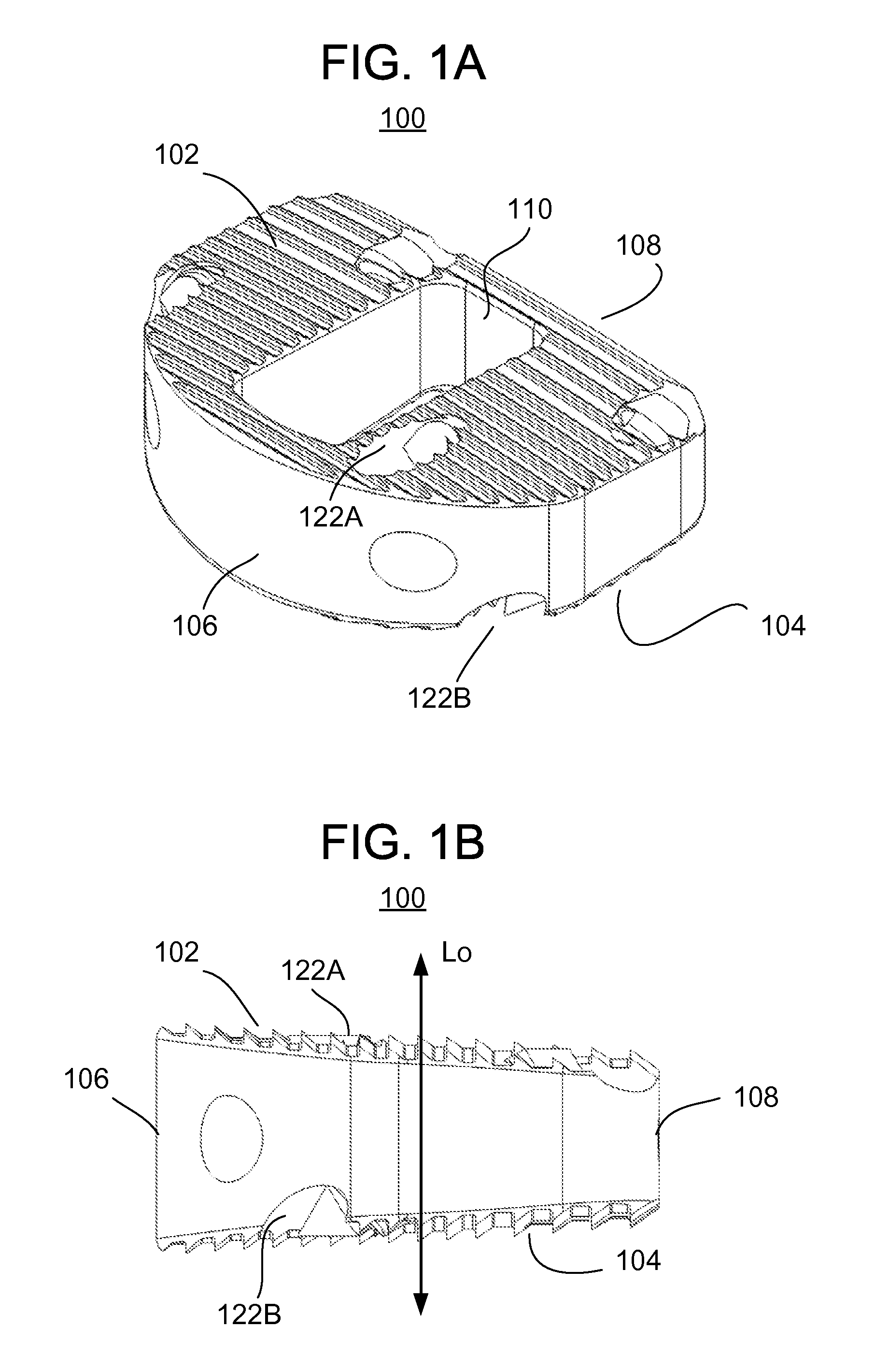
[0048]Reference is now made to FIGS. 1A and 1B, which illustrate an intervertebral prosthetic device 100 in accordance with one or more embodiments of the present invention. FIG. 1A illustrates a perspective view of the intervertebral device 100, while FIG. 1B is a lateral (side) view with the left of the drawing being in the front (anterior) direction and the right of the drawing being in the rear (posterior) direction. The body of the device may be made from any bio-compatible material, such as polyetheretherketone (PEEK), titanium, ceramic, etc.

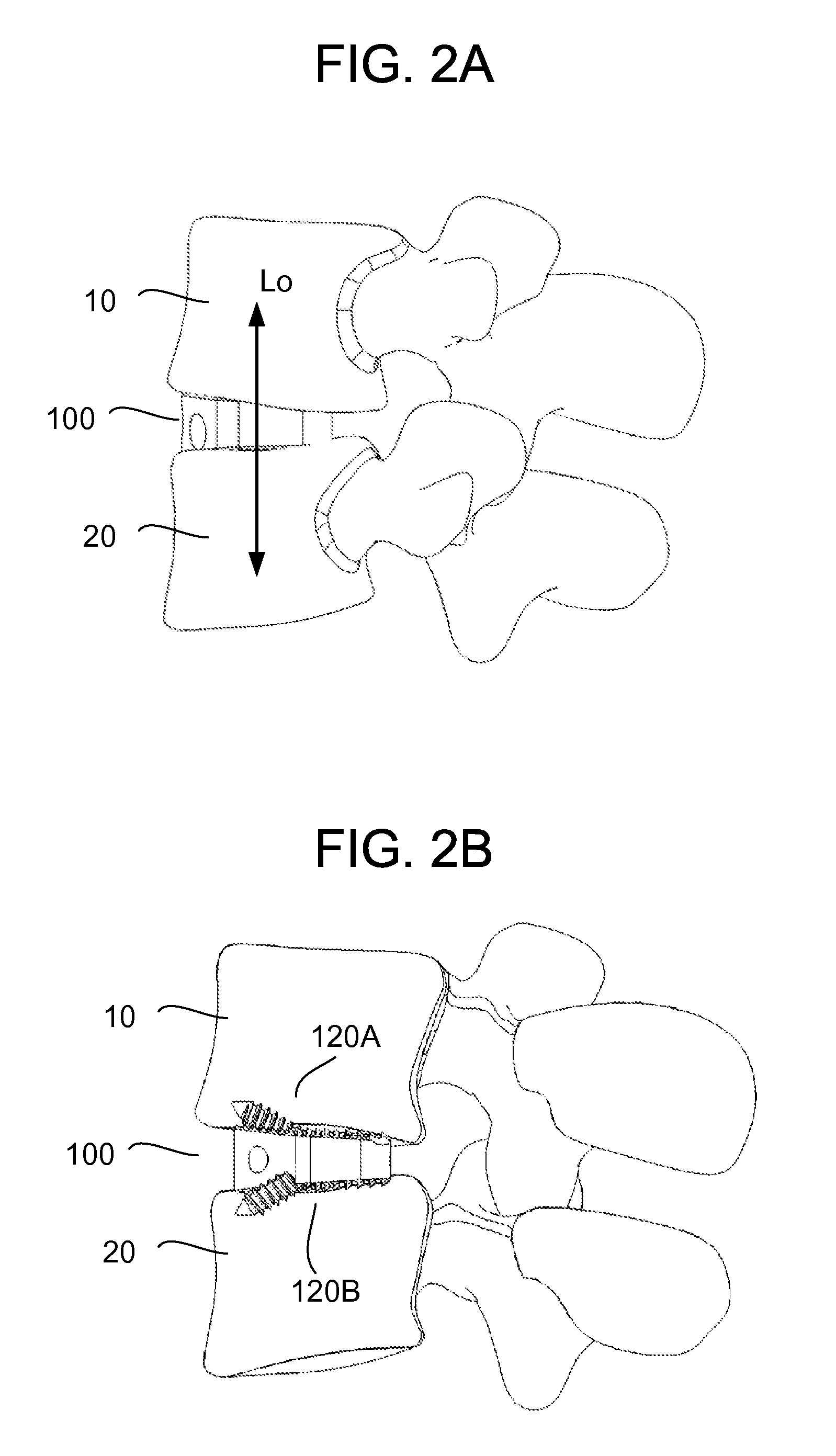
[0049]With further reference to FIG. 2A, which shows the device 100 in use, the device 100 generally includes a body (or housing) that is sized and shaped to fit in the intervertebral space between adjacent vertebral bones 10, 20 of the human spine. It is understood that the size and shape of the device 100 may be adapted to fit in an intervertebral space at any level of the spine, such as the cervical spine, thoracic spine, or lumbar spin...


PUM


Abstract

An apparatus for inserting an intervertebral prosthesis within a spine of a mammal includes: a handle including a drive nut operating to produce rotational torque in response to user-input about a central axis; a first drive shaft including a proximal end in communication with the drive nut, receiving rotational torque therefrom, and imparting rotational torque to the first drive shaft about a first axis, which is laterally offset from the central axis; and a distal end of the first drive shaft including a first drive head; and a chuck disposed at a distal end of the tool for engaging the intervertebral prosthesis during implantation, wherein the first drive shaft extends through the chuck and the first drive head engages a first gear of the intervertebral prosthesis, such that rotation of the first gear causes rotation and deployment of a first anchoring element of the intervertebral prosthesis.

Description

CROSS REFERENCE TO RELATED APPLICATIONS[0001]This application is a Continuation application of U.S. patent application Ser. No. 12 / 553,740, filed Sep. 3, 2009, now allowed, which is a Continuation-In-Part of U.S. patent application No. Ser. No. 12 / 339,766, filed Dec. 19, 2008, now pending, the entire disclosures of which are hereby incorporated by reference.BACKGROUND[0002]The present disclosure generally relates to apparatus and methods for treatment of spinal disorders using an intervertebral prosthesis which is disposed in an intervertebral space (or cavity) following removal of a damaged or diseased intervertebral disc.[0003]The bones and connective tissue of an adult human spinal column consists of more than twenty discrete bones coupled sequentially to one another by a tri-joint complex. Each tri-joint complex includes an anterior disc and two posterior facet joints. The anterior space between adjacent bones are cushioned by cartilage spacers referred to as intervertebral disc...

Claims


Application Information

Patent Timeline
Patent Type & Authority Applications(United States)
IPC IPC(8): A61F2/46
CPCA61F2/4611A61B17/86A61F2/4465A61F2/447A61F2002/2817A61F2002/2835A61F2002/30281A61F2002/30523A61F2002/30525A61F2002/30579A61F2002/30593A61F2002/30787A61F2002/30841A61F2002/30904A61F2002/4627A61F2002/4629A61F2220/0025A61F2230/0086A61F2310/00023A61F2310/00179
Inventor BERRY, BRET M.GUYER, RICHARD D.ZIGLER, JACKPIKE, ADAM A.LEE, RANDALL F.
Owner AMICUS DESIGN GRP LLC
Why Eureka
Eureka Blog
Learn More