Imaging member for offset printing applications

a technology of offset printing and imaging plates, applied in the field of imaging members, can solve the problems of not being able to accommodate true high-speed variable data printing, not being able to create and print new patterns from one page to the next, and the cost of permanently patterned imaging plates or cylinders is amortized over the number of copies

Active Publication Date: 2014-03-06
XEROX CORP
View PDF4 Cites 25 Cited by
  • Summary
  • Abstract
  • Description
  • Claims
  • Application Information

AI Technical Summary

Problems solved by technology

However, they do not permit creating and printing a new pattern from one page to the next without removing and replacing the print cylinder and/or the imaging plate (i.e., the technique cannot accommodate true high speed variable data pri

Method used


Image

  • Imaging member for offset printing applications
  • Imaging member for offset printing applications
  • Imaging member for offset printing applications

Examples


Embodiment Construction

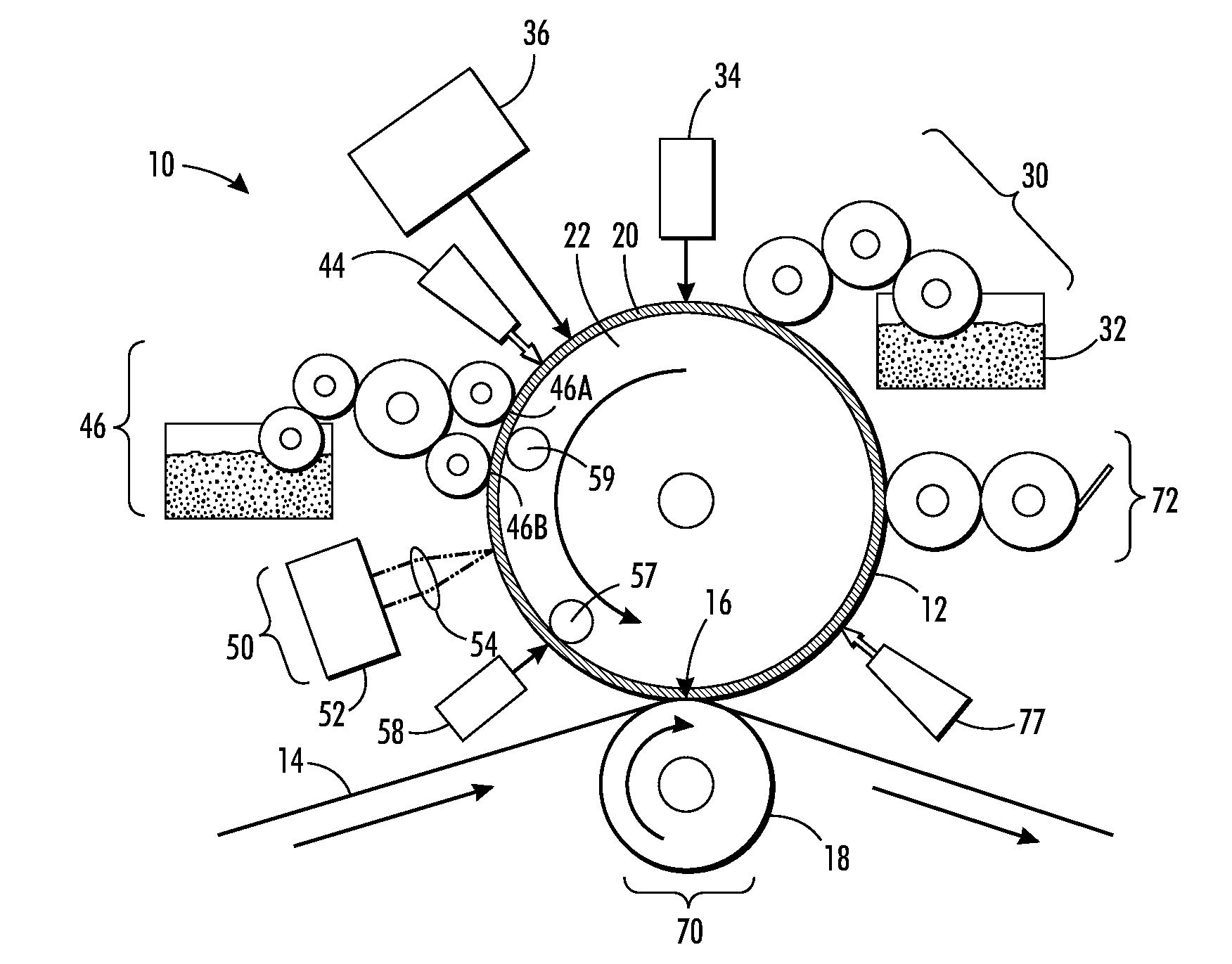
[0022]A more complete understanding of the processes and apparatuses disclosed herein can be obtained by reference to the accompanying drawings. These figures are merely schematic representations based on convenience and the ease of demonstrating the existing art and / or the present development, and are, therefore, not intended to indicate relative size and dimensions of the assemblies or components thereof.

[0023]Although specific terms are used in the following description for the sake of clarity, these terms are intended to refer only to the particular structure of the embodiments selected for illustration in the drawings, and are not intended to define or limit the scope of the disclosure. In the drawings and the following description below, it is to be understood that like numeric designations refer to components of like function.

[0024]The modifier “about” used in connection with a quantity is inclusive of the stated value and has the meaning dictated by the context (for example,...


PUM

PropertyMeasurementUnit
Temperatureaaaaaaaaaa
Percent by massaaaaaaaaaa

Abstract

An imaging member includes a surface layer comprising a fluoroelastomer-fluorosilicone composite. Methods of manufacturing the imaging member and processes for variable lithographic printing using the imaging member are also disclosed.

Description

RELATED APPLICATION[0001]The disclosure is related to U.S. patent application Ser. No. 13 / 095,714, filed on Apr. 27, 2011, titled “Variable Data Lithography System”, the disclosure of which is incorporated herein by reference in its entirety.FIELD OF DISCLOSURE[0002]The present disclosure is related to imaging members having a surface layer as described herein. The imaging members are suitable for use in various marking and printing methods and systems, such as offset printing. The present disclosure permits methods and systems providing control of conditions local to the point of writing data to a reimageable surface in variable data lithographic systems. Methods of making and using such imaging members are also disclosed.BACKGROUND[0003]Offset lithography is a common method of printing today. (For the purposes hereof, the terms “printing” and “marking” are interchangeable.) In a typical lithographic process a printing plate, which may be a flat plate, the surface of a cylinder, or...

Claims


Application Information

Patent Timeline
IPC IPC(8): C08F259/08G02B5/22B41F1/18B05D3/02B82Y30/00
CPCB41M1/06B41M1/02B41N10/00B41N2210/14B41P2227/70B82Y30/00G02B5/208G02B5/22
Inventor GERVASI, DAVID J.KANUNGO, MANDAKINIBADESHA, SANTOKH S.
Owner XEROX CORP
Why Eureka
Try Eureka