Motor control system and control system for electric motor-driven vehicle

a technology of motor control system and control system, which is applied in the direction of starter details, battery/fuel cell control arrangement, dynamo-electric converter control, etc., can solve the problems of driver turning off the key switch, difficult to make the vehicle move on its own to a desired location to pull over, and inability to drive the vehicle by the drive motor, etc., to achieve the effect of increasing the travelling rang

Active Publication Date: 2014-03-06
KANZAKI KOKYUKOKI MFG
View PDF5 Cites 28 Cited by
  • Summary
  • Abstract
  • Description
  • Claims
  • Application Information

AI Technical Summary

Benefits of technology

[0011]At least one of the advantages of the present invention is to provide, with respect to a motor control system, a driver a chance to pull over when the amount of charge of an electric power storage unit to which a drive motor and an auxiliary motor are connected is reduced, and to increase the travelling range after providing the chance.
[0012]Furthermore, at least one of the advantages of the present invention is to prevent, with respect to the motor control system, occurrence of a situation which is not desirable with respect to the durability of a part even in a case where a manual switch is turned off during rotation of at least one of the drive motor and the auxiliary motor.
[0013]Moreover, at least one of the advantages of the present invention is to alleviate or remove overload swiftly in a case where at least one of the drive motor and the auxiliary motor is overloaded in a control system for the electric motor-driven vehicle, and to protect the motor.

Problems solved by technology

In this case, the vehicle cannot be driven by the drive motor, and it becomes difficult to make the vehicle move on its own to a desired location to pull over, such as a repair garage.
However, there is a possibility that the driver turns off the key switch by mistake while driving the vehicle or a device to be driven by a motor.
If the controller is immediately turned off in this state, because at least one motor is not controlled while the motor is rotating, there possibly arises a situation which is not desirable with respect to the durability of the motor or a part such as an inverter connected to the motor.

Method used


Image

  • Motor control system and control system for electric motor-driven vehicle
  • Motor control system and control system for electric motor-driven vehicle
  • Motor control system and control system for electric motor-driven vehicle

Examples


first embodiment

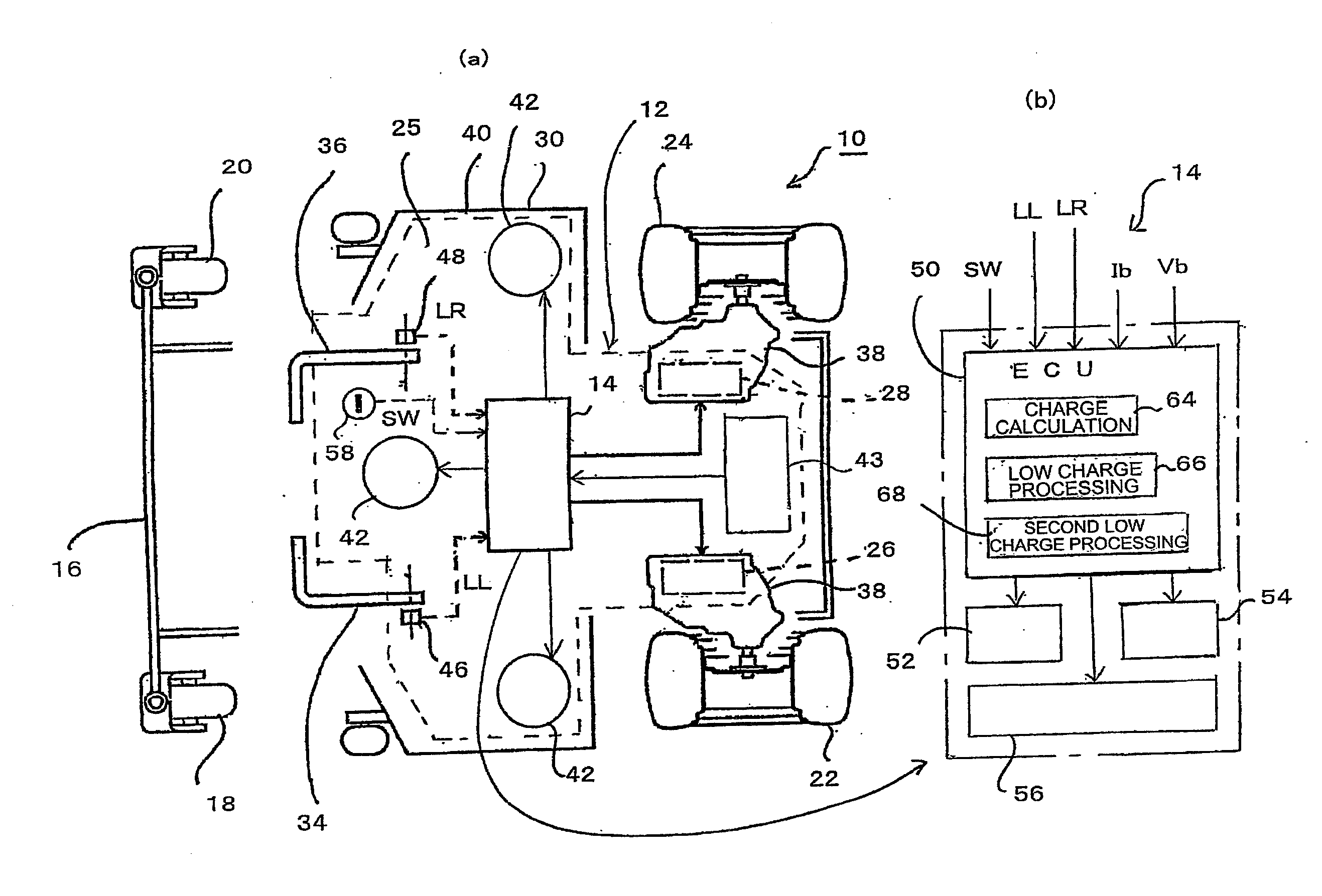
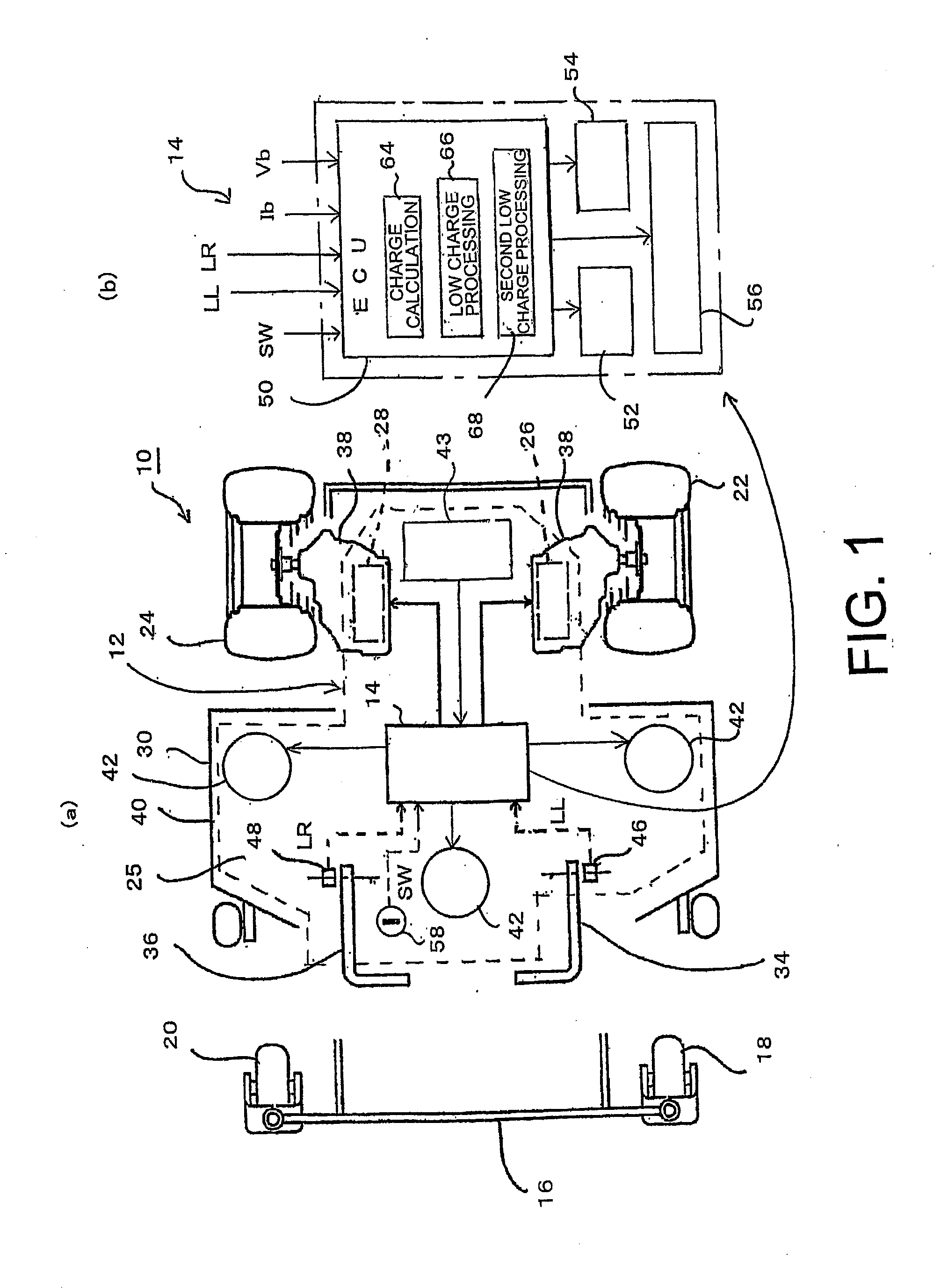
[0054]Hereinafter, embodiments of the present invention will be described in detail by reference to the drawings. In first to fourth embodiments, and embodiments of FIGS. 15 to 32 and 34, a case will be mainly described where a mower vehicle includes, as a structure having the functions of both a turning instruction device and an acceleration instruction device, a left / right lever-type operator including two operation levers, left and right operation levers, but this is only an example, and it is also possible to use a steering operator which is a steering handle as the turning instruction device, and an accelerator pedal which is an operator provided at the front side of a seat as the acceleration instruction device. Also, in the first to fourth embodiments, and embodiments of FIGS. 15 to 32 and 34, a case will be described where three deck motors, which are auxiliary motors, are provided to the mower vehicle, but one, two, or four or more deck motors may be provided. Moreover, in ...

second embodiment

[0104]FIG. 6 is a flow chart showing a method of controlling a drive motor and a deck motor in a control system of a second embodiment of the present invention. In the following description, elements identical with those shown in FIGS. 1 and 2 are denoted with the same reference numerals. The basic configuration of the present embodiment is the same as that of the first embodiment described above. In the present embodiment, the key switch 58 is not used as the restart permission section. Instead, the low charge processing unit 66 of the ECU 50 executes a “deck lock mode” of performing a step of disabling the deck motors 42 when the SOC, which is the amount of charge of the battery 43, reaches or falls below the first threshold Tsoc1 set in advance. When the SOC of the battery 43 reaches or falls below the second threshold Tsoc2 lower than the first threshold Tsoc1 after the deck motors 42 have been disabled, the low charge processing unit 66 executes the “low power mode,” which is a...

third embodiment

[0112]FIG. 8 is a flow chart showing a method of controlling a drive motor and a deck motor in a control system of a third embodiment of the present invention. The basic configuration of the present embodiment is the same as that of the first embodiment described above. Also in the present embodiment, the key switch 58 is not used as the restart permission section. Instead, the low charge processing unit 66 of the ECU 50 executes the “deck lock mode” of performing a step of disabling the deck motors 42 when the SOC, which is the amount of charge of the battery 43, reaches or falls below the first threshold Tsoc1 set in advance. Also, when the SOC of the battery 43 reaches or falls below the second threshold Tsoc2 lower than the first threshold Tsoc1 after the deck motors 42 have been disabled, the low charge processing unit 66 performs the “motor disabling step” of disabling the drive motors 26 and 28.

[0113]When the SOC of the battery 43 reaches or falls below the first threshold Ts...


PUM


Abstract

A motor control system includes a drive motor and a deck motor that are connected to a battery, an ECU, and a key switch. The key switch acquires that an operation unit has been turned on, and transmits a restart permission signal to the ECU. When SOC of the battery reaches or falls below a first threshold set in advance, the ECU performs a step of disabling all the motors, and when the restart permission signal is received, the ECU performs a step of executing a decelerated travelling mode where the disabled state of the drive motor is released and an allowed speed of the drive motor is reduced.

Description

PRIORITY INFORMATION[0001]Japanese Patent Application No. 2012-188266 filed on Aug. 29, 2012, Japanese Patent Application No. 2012-198243 filed on Sep. 10, 2012, and Japanese Patent Application No. 2012-268076 filed on Dec. 7, 2012 are identified and incorporated herein.BACKGROUND[0002]1. Technical Field[0003]The present invention relates to a motor control system including a drive motor, an auxiliary motor, and a controller. The present invention also relates to a control system for a motor-driven vehicle including the drive motor and the auxiliary motor, a drive motor controller for controlling the drive motor, an auxiliary motor controller for controlling the auxiliary motor, and a main controller.[0004]2. Related Art[0005]A mower vehicle including a mower which is a working implement that is driven to perform mowing, is conventionally known. With respect to such a mower vehicle, it is conceivable to configure a motor-driven vehicle where left and right wheels, which are main dri...

Claims


Application Information

Patent Timeline
Patent Type & Authority Applications(United States)
IPC IPC(8): H02P1/02H02P3/02
CPCH02P3/02H02P1/021B60L2200/40A01D34/78H02P29/032H02P29/60B60L58/12Y02T10/70Y02T10/72Y02T10/64H02P5/68H02P29/028
Inventor WANG, HONGKUNKOGA, KAZUNARINAKAGAWA, SHIGEAKIISHINO, FUMITOSHICASS, WILLIAM J.
Owner KANZAKI KOKYUKOKI MFG
Why Eureka
Try Eureka