Method and apparatus for driving a sensorless bldc/pmsm motor

a sensorless, brushless direct current technology, applied in the direction of motor/generator/converter stopper, electronic commutator, dynamo-electric converter control, etc., can solve the problems of increased complexity, increased component cost, and reduced reliability

Active Publication Date: 2014-03-06
MELEXIS TECH NV
View PDF5 Cites 20 Cited by
  • Summary
  • Abstract
  • Description
  • Claims
  • Application Information

AI Technical Summary

Benefits of technology

[0007]It is an object of embodiments of the present invention to provide a good method and device for dri

Problems solved by technology

This, however, has the disadvantage of increased complexity, extra component cost and decreased reliability, especially in harsh motor environments.
A disadvantage of such methods is that they require

Method used


Image

  • Method and apparatus for driving a sensorless bldc/pmsm motor
  • Method and apparatus for driving a sensorless bldc/pmsm motor
  • Method and apparatus for driving a sensorless bldc/pmsm motor

Examples


Embodiment Construction

[0071]The present invention will be described with respect to particular embodiments and with reference to certain drawings but the invention is not limited thereto but only by the claims. The drawings described are only schematic and are non-limiting. In the drawings, the size of some of the elements may be exaggerated and not drawn on scale for illustrative purposes. The dimensions and the relative dimensions do not correspond to actual reductions to practice of the invention.

[0072]The terms first, second and the like in the description and in the claims, are used for distinguishing between similar elements and not necessarily for describing a sequence, either temporally, spatially, in ranking or in any other manner. It is to be understood that the terms so used are interchangeable under appropriate circumstances and that the embodiments of the invention described herein are capable of operation in other sequences than described or illustrated herein.

[0073]Moreover, the terms top,...


PUM


Abstract

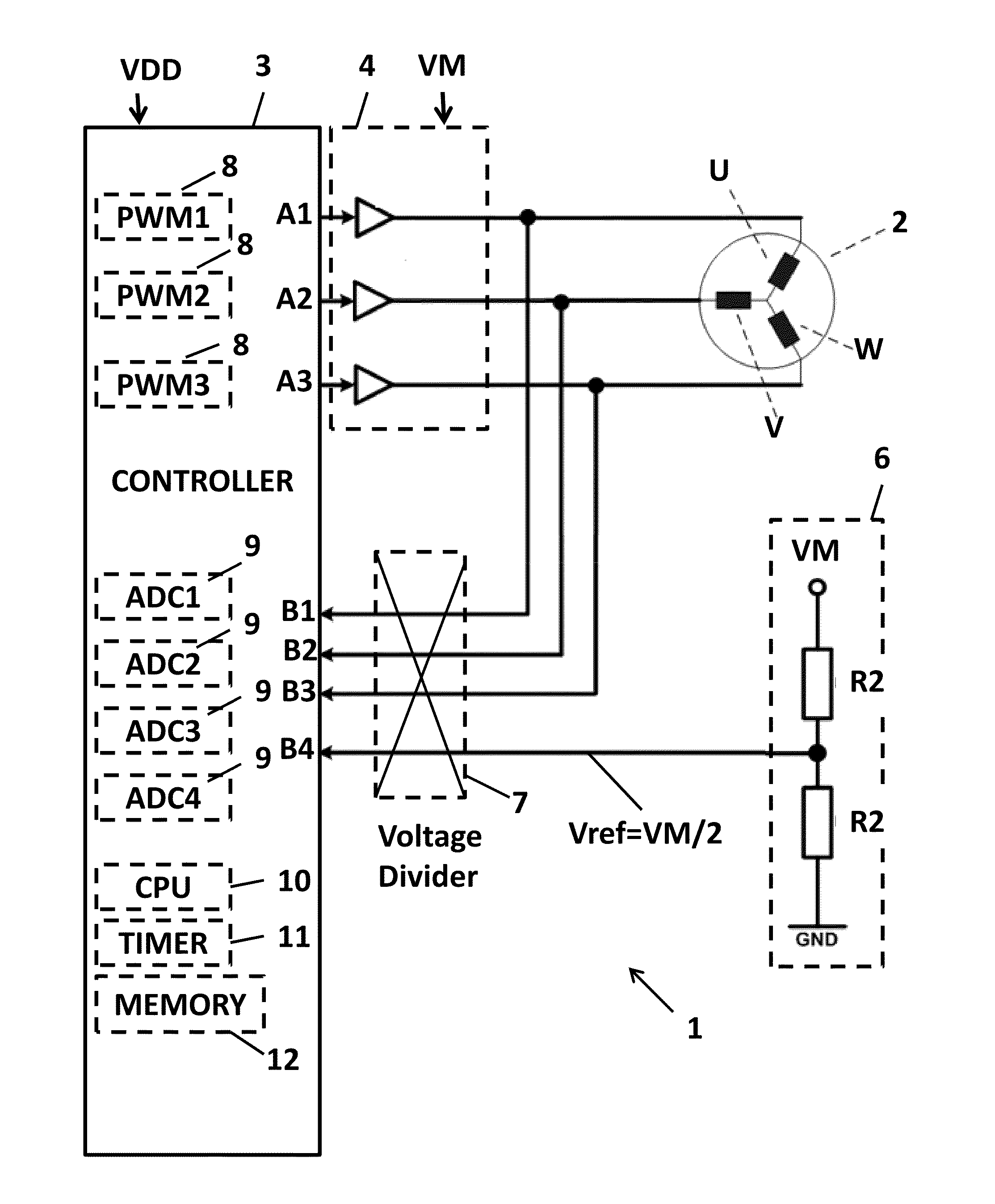
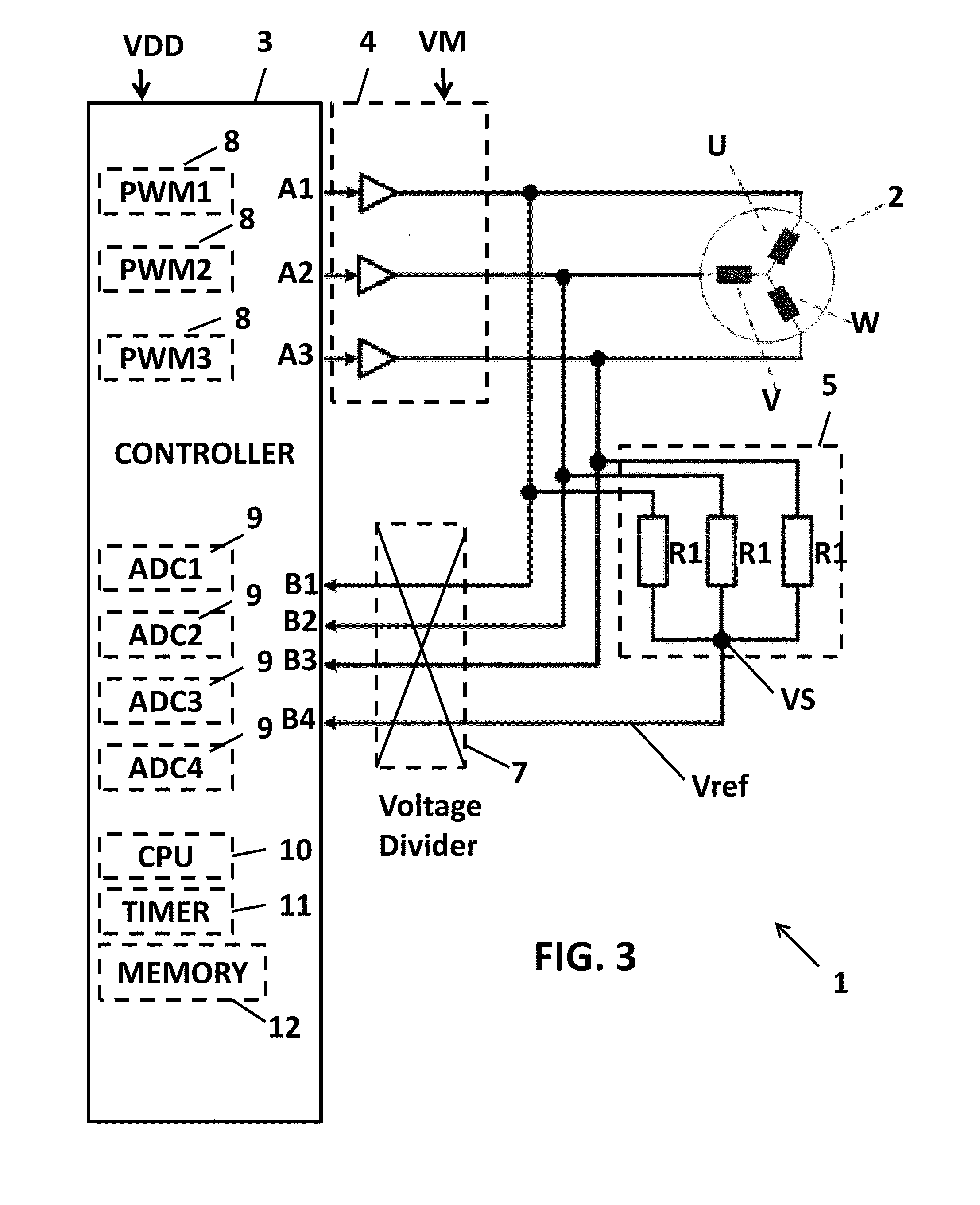
A method for driving a BLDC motor comprising at least three stator windings, comprising: a) determining a time period, and energizing during the time period two of the windings and leaving a third winding un-energized, based on a first motor state; b) measuring a first voltage representative for the back-EMF generated in the un-energized winding shortly before expiry of the time period; c) applying a commutation at expiry of the current time period; d) measuring a second voltage shortly after the commutation, and calculating a subsequent time period; e) repeating steps b) and c). An electrical circuit and a controller are provided for performing these methods.

Description

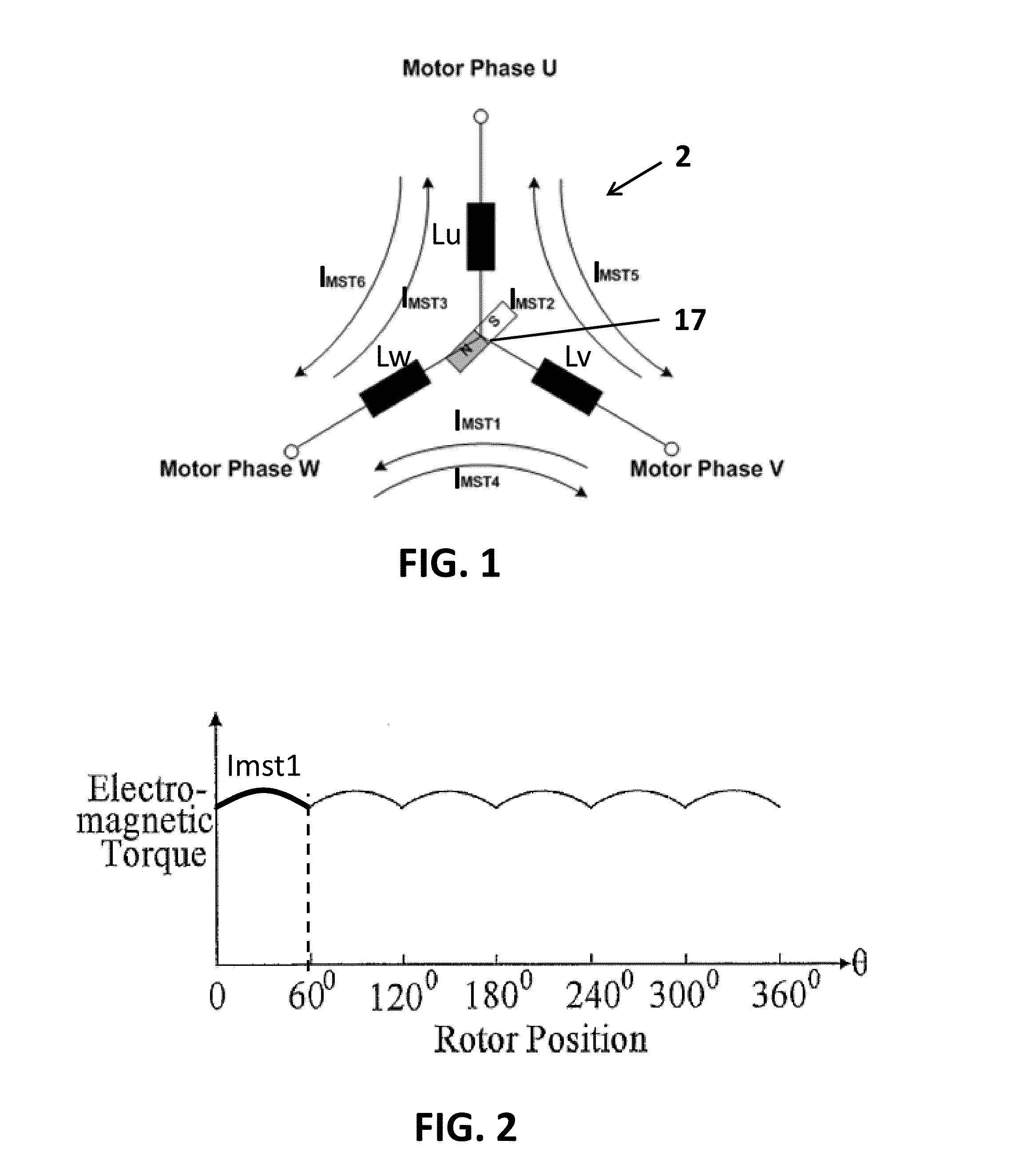
FIELD OF THE INVENTION[0001]The invention relates to the field of sensorless brushless direct current (BLDC) motors. In particular, the present invention provides a method and apparatus for starting and running such a motor.BACKGROUND OF THE INVENTION[0002]Brushless Direct Current (BLDC) motors are a type of electrical motor having multiple status phases (e.g. three or more) and a permanent magnet as a rotor (e.g. a bar magnet or a multi-pole magnet). BLDC motors do not use brushes for commutation, but instead they are electronically commutated. This implies, however, that the drive circuit must know the relative position of the rotor with respect to the stator, in order to direct the magnetic field for exerting torque on the rotor.[0003]One kind of BLDC motors uses sensor devices such as e.g. optical sensor devices or Hall elements positioned around the rotor for determining the relative position using a resolver. This, however, has the disadvantage of increased complexity, extra c...

Claims


Application Information

Patent Timeline
IPC IPC(8): H02P6/18
CPCH02P6/182H02P6/30
Inventor PETRI, VIKTORFREITAG, THOMAS
Owner MELEXIS TECH NV
Why Eureka
Try Eureka