Magnetic sensor and biomagnetism measurement system

a technology applied in the field of magnetic sensor and biomagnetism measurement system, can solve the problem of insufficient measurement of magnetic shielded room

Active Publication Date: 2014-03-06
SPIN SENSING FACTORY CORP
View PDF4 Cites 35 Cited by
  • Summary
  • Abstract
  • Description
  • Claims
  • Application Information

AI Technical Summary

Benefits of technology

[0033]According to the present invention, the assemblies having the tunnel magnetoresistive elements, the fixed magnetic layers of which are disposed to have a relative angle of at least more than 90° (preferably substantially 180°) to be opposite to each other, oppositely change their respective resistance values with respect to a large eternal magnetic field or a uniform magnetic field derived from magnetism relatively widely emitted from a human body which is not a detection target, thereby cancelling out the changes of the resistance values. Hence, a resistance value of a component in which these are connected to each other in series and / or in parallel is a constant value. On the other hand, with respect to a weak magnetic field emitted from a detection target (for example, a brain) and locally different, the assemblies show different changes of the resistance values, which are not cancelled out, and this is detected. That is, biomagnetic signals of a detection target can be detected.

Problems solved by technology

Although the magnetism shielded room can shield large external magnetic fields (coarse magnetic fields), as with a magnetic field emitted from a heart being noise in neuromagnetic field measurement, a magnetic field emitted from a living body could be noise for biomagnetic signals of a detection target.
Thus, the magnetism shielded room may be an insufficient measure.

Method used


Image

  • Magnetic sensor and biomagnetism measurement system
  • Magnetic sensor and biomagnetism measurement system
  • Magnetic sensor and biomagnetism measurement system

Examples


Embodiment Construction

[0059]In the following, an embodiment of the present invention is described with reference to the drawings. The following is an embodiment of the present invention and hence does not intend to limit the present invention.

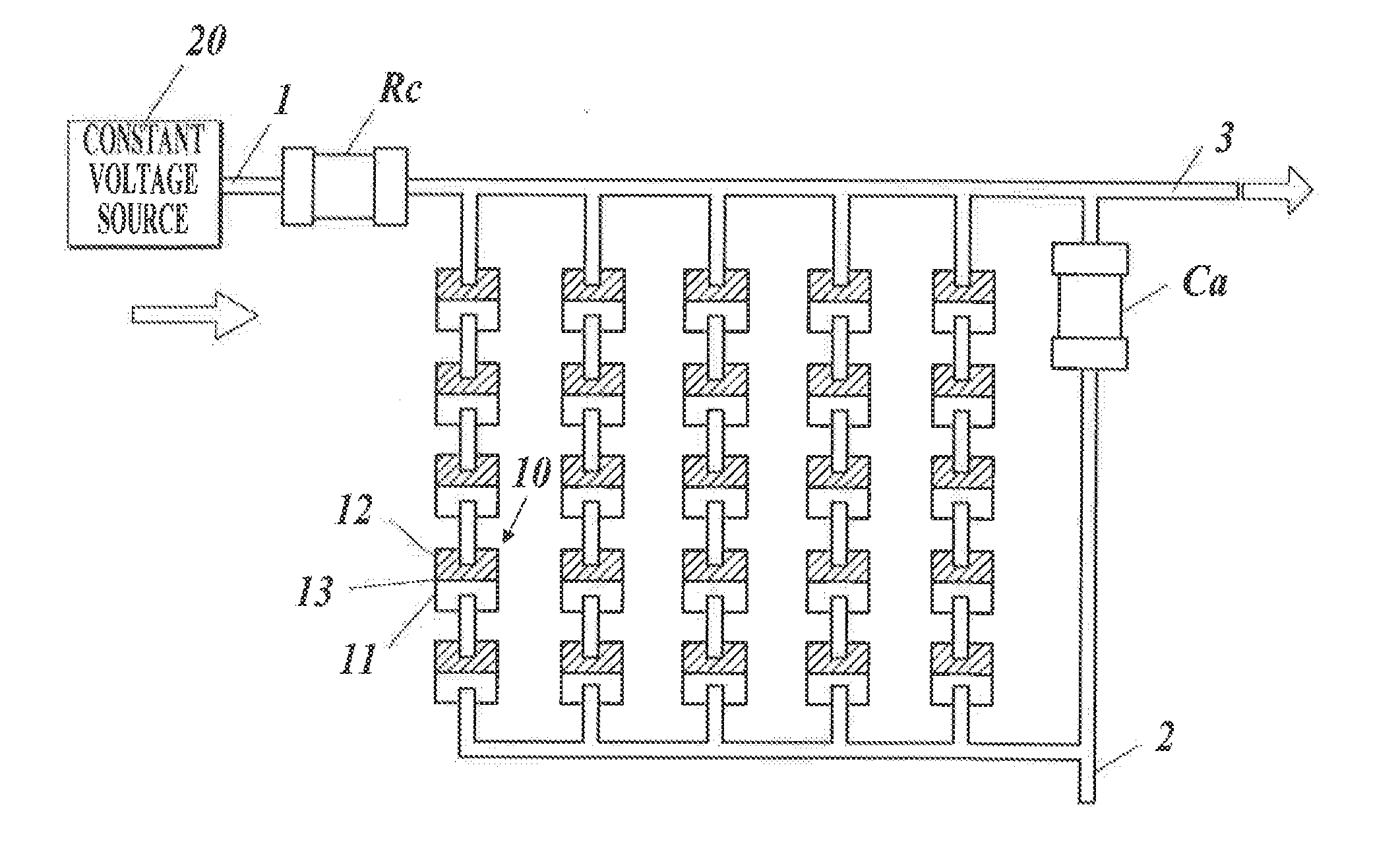
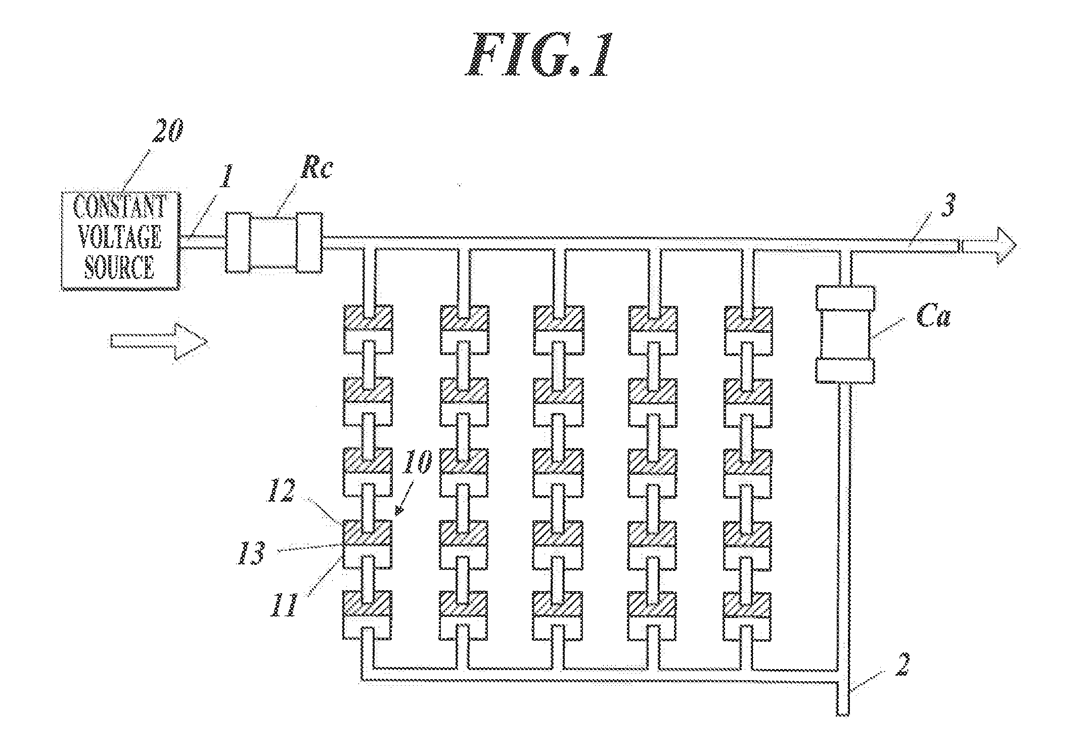
[0060]A magnetic sensor of the embodiment is formed by combining a plurality of assemblies each having a circuit configuration shown in FIG. 1.

[0061]Each assembly includes: a plurality of tunnel magnetoresistive elements 10 connected to each other in series-parallel; a capacitor Ca connected to the tunnel magnetoresistive elements 10 in parallel; and a fixed resistor Rc connected to the tunnel magnetoresistive elements 10 and the capacitor Ca in series. Hereinafter, “in series-parallel” means that sets of tunnel magnetoresistive elements 10 connected to each other in series are connected to each other in parallel, sets of tunnel magnetoresistive elements 20 connected to each other in parallel are connected to each other in series, or a combination thereof. (Refer to...


PUM


Abstract

A magnetic sensor includes a plurality of assemblies combined. Each assembly includes a plurality of tunnel magnetoresistive elements, a capacitor and a fixed resistor. The tunnel magnetoresistive elements are (i) disposed in such a way that fixed magnetization directions of fixed magnetic layers are substantially identical and changeable magnetization directions of free magnetic layers with no magnetic field applied are substantially identical and (ii) connected to each other in series-parallel. The capacitor is connected in parallel to the tunnel magnetoresistive elements. The fixed resistor is connected in series to the tunnel magnetoresistive elements and to the capacitor. The assemblies are (i) disposed in such a way that the fixed magnetization directions of the fixed magnetic layers of the assemblies have a relative angle of more than 90 degrees and (ii) connected to each other in series and / or in parallel.

Description

FIELD OF THE INVENTION[0001]The present invention relates to a magnetic sensor and a biomagnetism measurement system.BACKGROUND OF THE ART[0002]As a device to measure magnetism emitted from a living body, a biomagnetism measurement device using SQUID (Superconducting Quantum Interference Device) sensors has been researched (Patent Documents 1 to 5, for example). By arranging a large number of SQUID sensors and using the SQUID sensors to measure biomagnetism, two-dimensional magnetism information such as magnetoencephalograms or magnetocardiograms can be obtained.[0003]In order to measure biomagnetism with SQUID sensors, the SQUID sensors need to be maintained in a superconductive state with a refrigerant. Hence, SQUID sensors are placed in a Dewar flask where a refrigerant is stored and are used for the measurement in a state in which the SQUID sensors are soaked in the refrigerant.[0004]There has been proposed a biomagnetism measurement device in which a portion of the outer wall p...

Claims


Application Information

Patent Timeline
Patent Type & Authority Applications(United States)
IPC IPC(8): G01R33/09
CPCG01R33/093A61B5/6803A61B2562/0223A61B2562/046G01R33/098H01F10/3254A61B5/242A61B5/245
Inventor NISHIKAWA, TAKUO
Owner SPIN SENSING FACTORY CORP
Why Eureka
Try Eureka