Cell wiring module

a cell module and wiring technology, applied in the field of cell wiring modules, can solve the problems of dimensional errors in the cell module and possible mounting failure, and achieve the effect of preventing failure when mounting on a plurality of single cells

Inactive Publication Date: 2014-03-06
AUTONETWORKS TECH LTD +2
View PDF4 Cites 14 Cited by
  • Summary
  • Abstract
  • Description
  • Claims
  • Application Information

AI Technical Summary

Benefits of technology

[0030]According to the present invention, failure when mounting on a plurality of single cells can be prevented.

Problems solved by technology

However, an occurrence of dimensional errors in the cell module is not limited to spacing of electrodes connected by the bus bar (connection member).
In such a case, a mounting failure may occur not only due to a dimensional error in spacing between the electrodes, but also due to a dimensional error between the main body of the single cell and the cell wiring module.

Method used


Image

  • Cell wiring module
  • Cell wiring module
  • Cell wiring module

Examples


embodiment 1

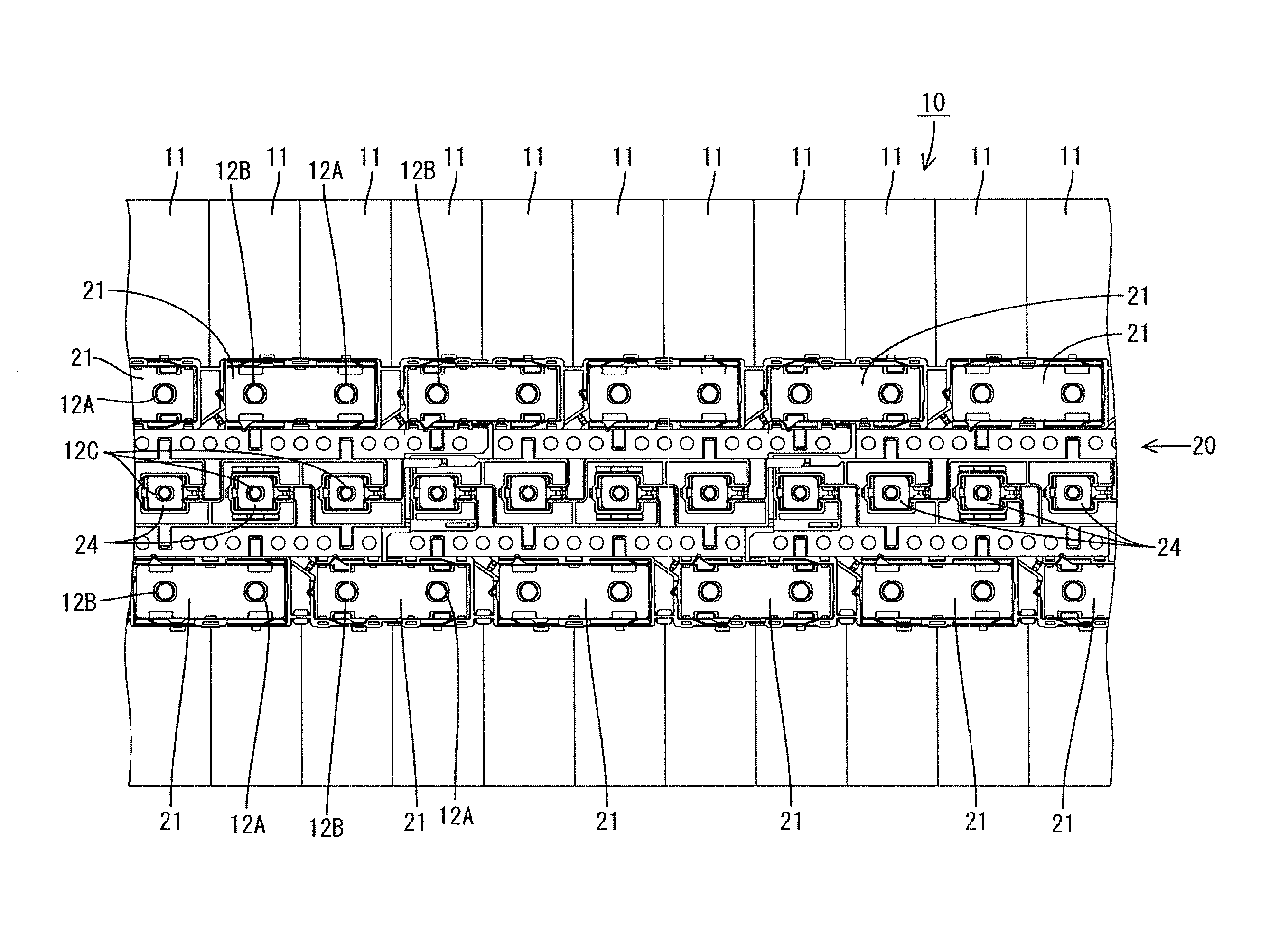
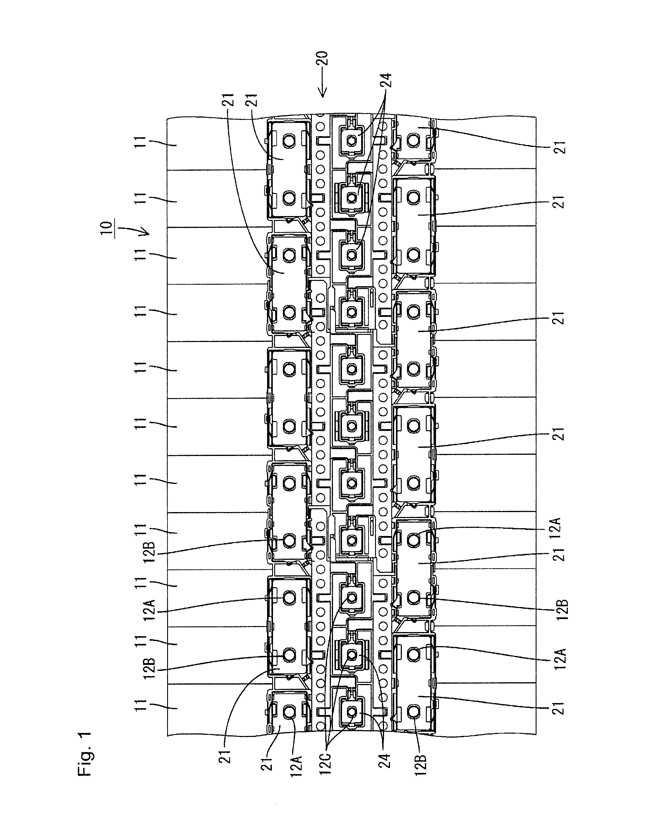
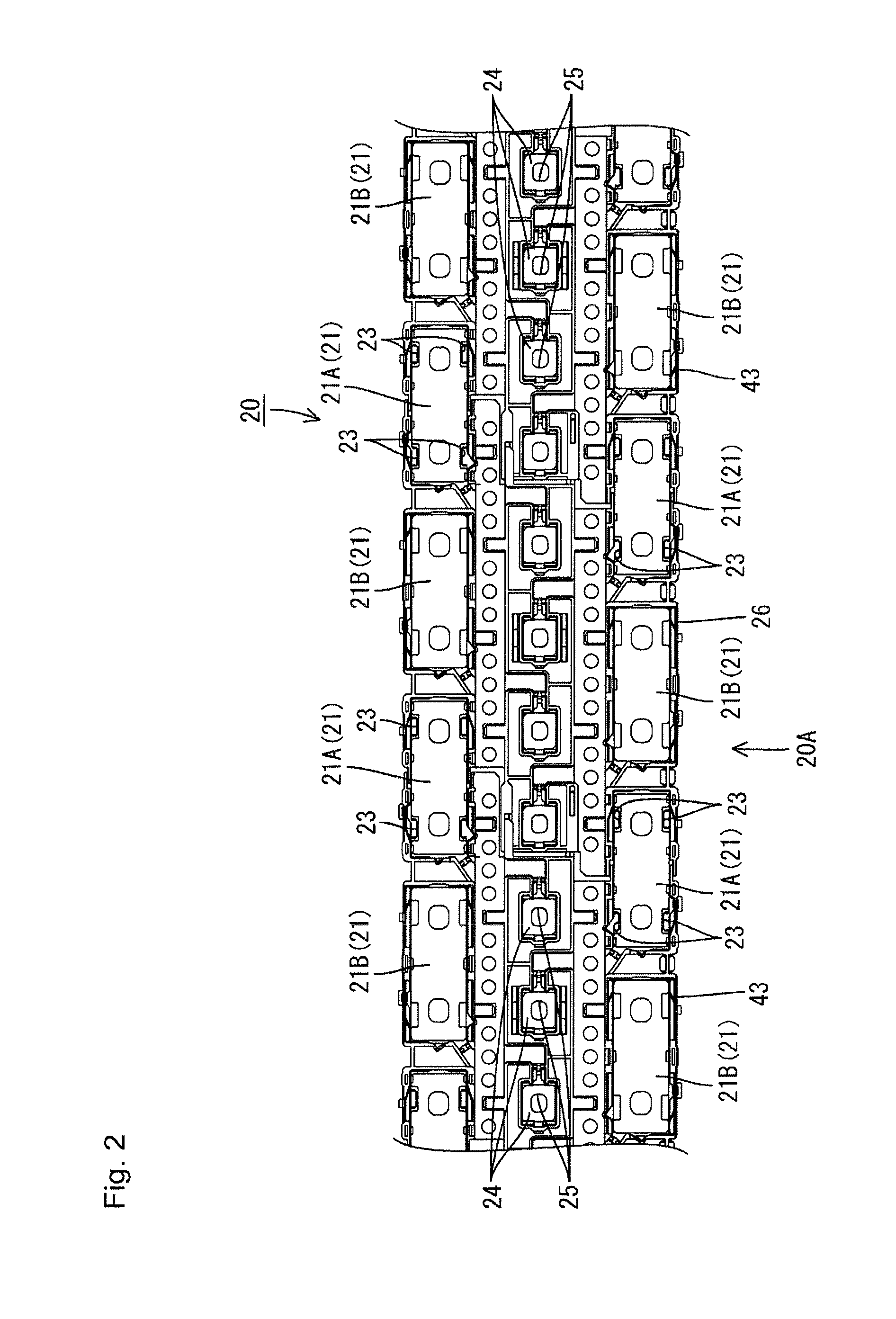
[0042]Hereafter, with reference to FIGS. 1 to 5, a description is given of an embodiment of the present invention. A cell wiring module 20 of the present embodiment connects, with a connection member 21, electrode terminals 12A and 12B of adjacent single cells 11. The cell wiring module 20 is attached to a cell module 10, which is used as a vehicle power source in an electric or hybrid automobile, for example. Hereafter, the description is given with upward in FIG. 1 treated as forward and downward treated as rearward for a front-back direction, while a near face of a sheet of FIG. 1 is treated as upward and a far face of the sheet is treated as downward for a vertical direction.

[0043](Cell Module)

[0044]As shown in FIG. 1, the cell module 10 is configured to include, for example, a plurality (eleven, in FIG. 1) of the single cells 11 (a bank of single cells) and the cell wiring module 20 connecting the plurality of single cells 11.

[0045](Single Cell)

[0046]The single cells 11 include...

embodiment 2

[0090]Embodiment 2 is described with reference to FIGS. 6 to 11. Hereafter, the description is given with upward in FIG. 6 treated as forward and downward treated as rearward for the front-back direction, while a near face of a sheet of FIG. 6 is treated as upward and a far face of the sheet is treated as downward for the vertical direction. Moreover, configurations identical to those of Embodiment 1 are given identical reference numerals and descriptions thereof are omitted.

[0091](Cell Module)

[0092]As shown in FIG. 6, a cell module 50 is configured to include, for example, ten (a plurality) of the single cells 11 and a cell wiring module 51 connecting the ten single cells 11. The ten single cells 11 are divided into three rows in a long axis (long side) direction of the top surface of the single cells 11 (a surface having the electrode terminals). Two rows on a left side are stacked in four layers in a short axis direction of the top surface of the single cells 11, and one row on a...


PUM

PropertyMeasurementUnit
shapesaaaaaaaaaa
rigidityaaaaaaaaaa
lengthaaaaaaaaaa

Abstract

A cell wiring module is configured to include a plurality of connection members connecting adjacent electrode terminals of a plurality of single cells having positive and negative electrode terminals. The cell wiring module includes a first unit housing a housed connection member, and a second unit connected to the first unit by a linking connection member different from the housed connection member. Sliding occurs in the connection direction of the connection members between the linking connection member for connection and at least one of the first unit and the second unit.

Description

FIELD OF THE INVENTION[0001]The present invention relates to a cell wiring module.BACKGROUND OF THE INVENTION[0002]A cell module for an electric vehicle or a hybrid car has a plurality of single cells stacked in rows, the single cells being configured by a main body having a flat shape and a power generating element on an interior thereof and by positive and negative electrode terminals. In addition, the plurality of single cells are connected serially or in parallel by connecting the electrode terminals of adjacent single cells with a connection member (bus bar).[0003]Thus, in a configuration of Patent Literature 1, noted below, a battery connection plate is disclosed which is configured by incorporating a plurality of bus bars by insert molding on a synthetic resin base board, and the battery connection plate is mounted on a plurality of cells, thereby integrally connecting the plurality of bus bars.[0004]In order to prevent failure in mounting the battery connection plate (cell w...

Claims


Application Information

Patent Timeline
Patent Type & Authority Applications(United States)
IPC IPC(8): H01M2/20H01M50/503H01M50/517
CPCH01M2/206H01M50/517H01M50/503H01M2220/20Y02E60/10
Inventor NAKAYAMA, OSAMU
Owner AUTONETWORKS TECH LTD
Why Eureka
Try Eureka