Mechanical wound therapy for sub-atmospheric wound care system

a mechanical and sub-atmospheric technology, applied in the field of patient wound care, can solve the problems of inability to provide this mode of wound cleansing, inability to readily perform modern wound care elements, and inability to provide this mode of wound care, so as to reduce the need for additional surgical debridement, reduce the risk of infectious complications, and effectively treat specific wounds.

Active Publication Date: 2014-03-06
J&M SHULER MEDICAL
View PDF4 Cites 63 Cited by
  • Summary
  • Abstract
  • Description
  • Claims
  • Application Information

AI Technical Summary

Benefits of technology

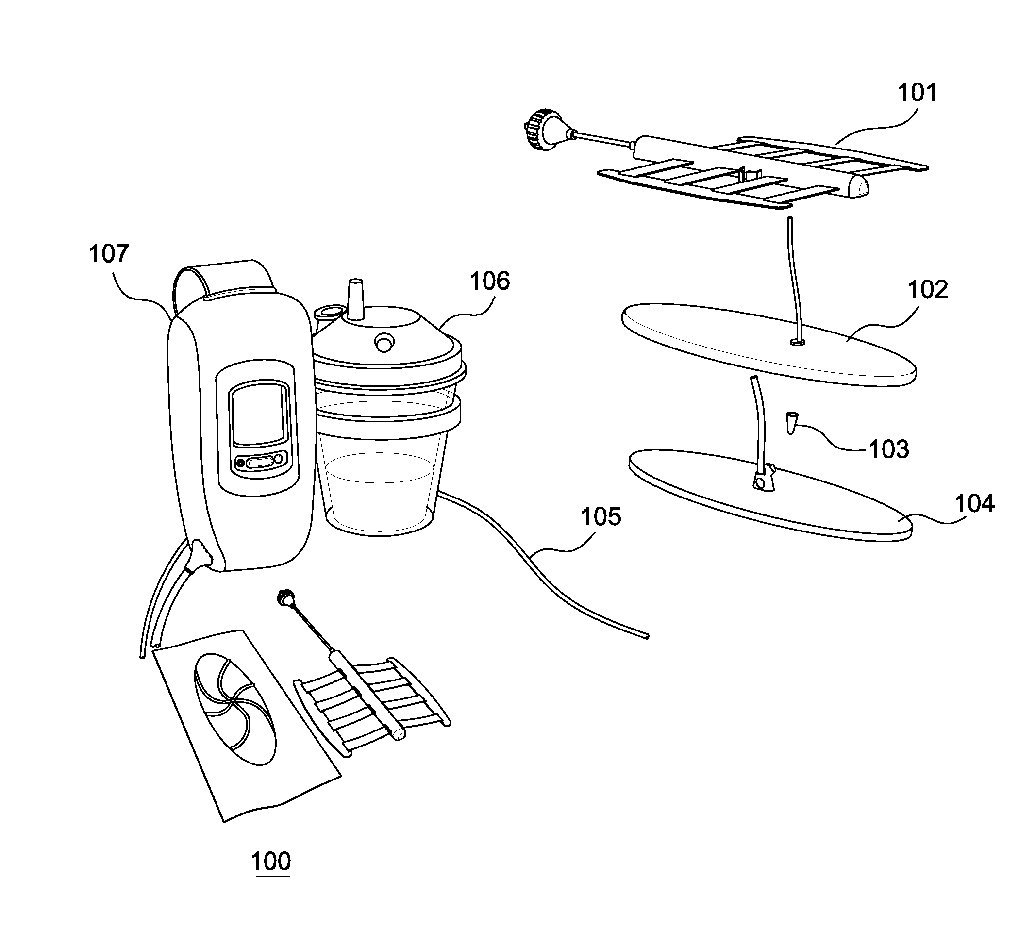
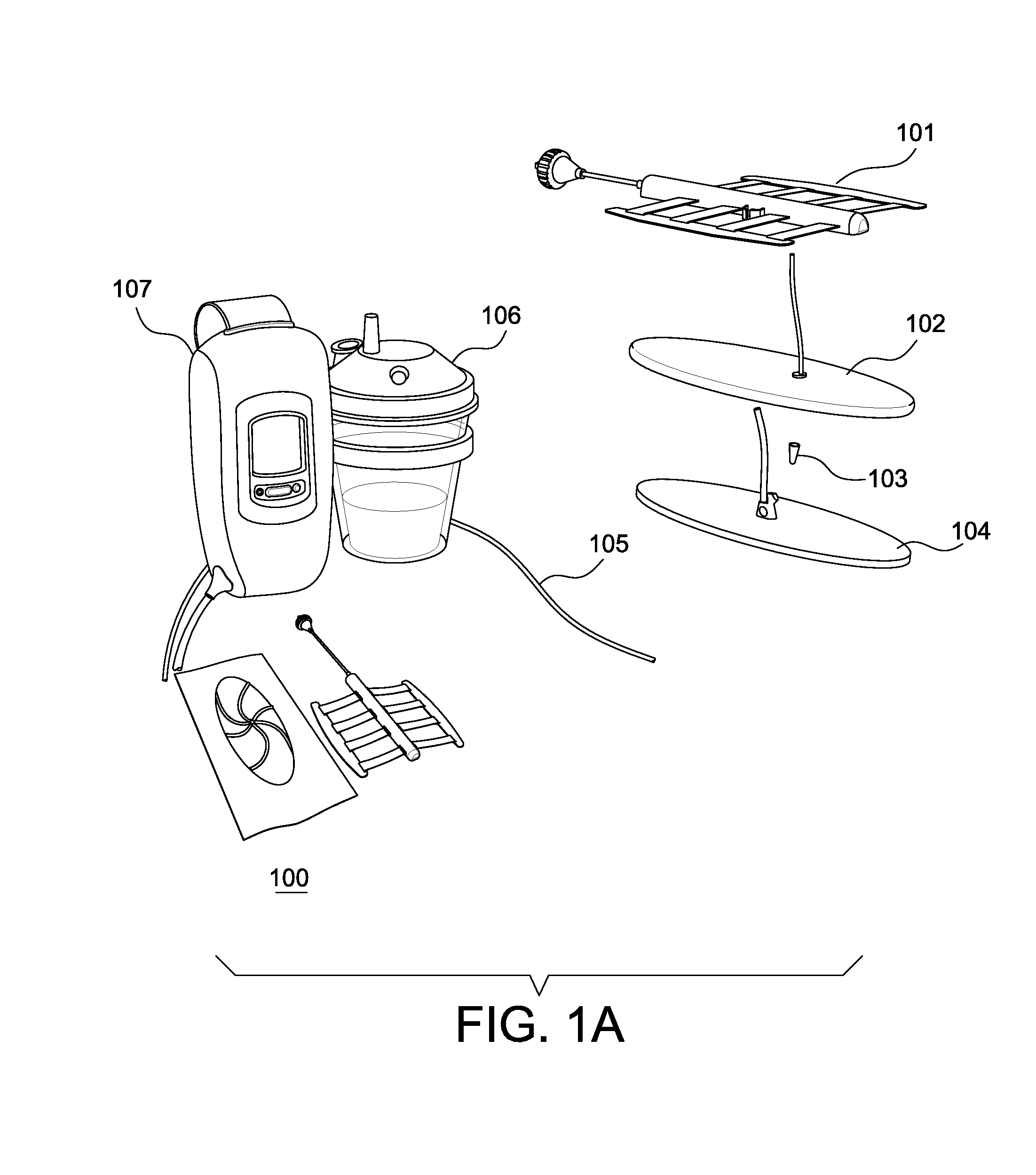
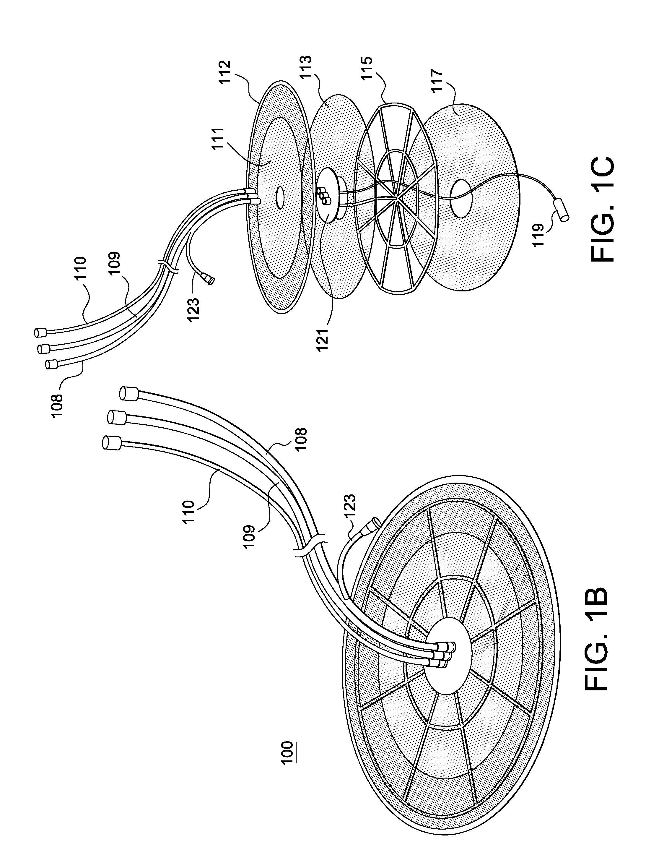
[0013]In contrast to conventional designs, various embodiments disclosed herein are unique in the delivery of the irrigant and the pathway the irrigant must travel to reach the completely separate vacuum circuit. Irrigant is typically delivered directly to the periphery of the wound. By doing this, the irrigant is forced to travel across the wound surface to reach the vacuum portion of the system which is located in the central aspect of the dressing. Without direct delivery of the irrigant to the periphery, the irrigant will follow the path of least resistance, which is generally a direct route back to the vacuum source. Additionally, under the reverse pulse lavage mechanism, the driving force behind the irrigation is not a positive injecting force, which can allow for pooling and compromise of the airtight seal, instead irrigate is pulled in a controlled fashion by bursts of negative pressure from the vacuum circuit. By allowing suction to drive the delivery of the irrigant with short pulses of negative pressure, the irrigant is unlikely to pool and compromise the seal at the periphery of the dressing. The current inventors describe a novel irrigation delivery method for ensuring the entire wound is irrigated while also limiting the potential detrimental effects of allowing irrigant to pool and compromise the seal.
[0021]While the MWT concept includes aspects of care that are contained in NPWT system in a segregated manner, these parts are part of an overall integrated system in the MWT. This integrated treatment of MWT provides benefits not available using simple NPWT. For example, without MWT's approach of integrating these additions into a single system, the dressing typically cannot remain in place on the wound on for prolonged periods, for example, for periods as long as 48 to 72 hours, or longer. Further, by using MWT the dressing acts to cleanse the wound, thereby reducing the need for additional surgical debridement and / or reducing risk of infectious complication. Moreover, the dressing in conventional NPWT systems on its own only minimally, if at all, contributes towards directly reducing the dimensions of the wound, and these conventional dressing cannot provide wound monitoring. These elements are not attainable in any other fashion than through the integration of the various embodiments disclosed herein.

Problems solved by technology

Operating in such a segregated manner is often disadvantageous in terms of consistency, efficiency and efficacy of wound care.
Further, some elements of modern wound care cannot readily be performed without integration of the component parts into the MWT system.
This design flaw prohibits lavage irrigation, in which bursts of vacuum and irrigation run simultaneously or near-simultaneously under the control of the programmable electronic vacuum regulator.
Conventional art that shares tubing or other forms of flow-path between vacuum (out-flow) and irrigation (in-flow) cannot provide this mode of wound cleansing.
This design drawback further makes lavage irrigation impossible for conventional devices, which “instill” irrigant to the surface of the dressing not facing the wound, and allow or hope for irrigant to soak through the dressing material to reach the underlying wound.
This method only ensures wetting of the wound filler, which does not replicate the elements of irrigation used currently in open surgical procedures.

Method used


Image

  • Mechanical wound therapy for sub-atmospheric wound care system
  • Mechanical wound therapy for sub-atmospheric wound care system
  • Mechanical wound therapy for sub-atmospheric wound care system

Examples


Embodiment Construction

[0054]The present inventors recognized that the management of open wounds from trauma or disease, with the assistance of NPWT, benefits from the application of multiple features of the embodiments disclosed herein. From the time the wound is created it is beneficial if several interim activities occur prior to the final step in wound care, definitive soft tissue management. These interim activities include irrigation and debridement, minimization of microbial load, monitoring of the wound and sequential approximation of the wound—that is, closing of the wound—to the extent possible.

[0055]Typically, it is recognized that a wound care system cannot act completely independent of provider directed wound care. Surgical irrigation, gross wound decontamination, and debridement will remain the hallmarks of initial wound care in the foreseeable future. However, the present inventors recognized a number of improvements that aid in the development of a robust MWT integrated systems. Various em...


PUM

PropertyMeasurementUnit
diameteraaaaaaaaaa
diameteraaaaaaaaaa
thicknessaaaaaaaaaa

Abstract

A mechanical wound therapy (MWT) system includes a connection for a vacuum source, which is routed through an airtight covering to a porous material positioned over the wound. The porous material may be a tubing network interspaced by a netting material constructed of biologically inert or bioabsorbable material. Alternatively, the porous material may be a layered unified dressing in which layers of mesh, netting or thin perforated film are separated and fixedly attached to functional elements of the dressing (e.g., irrigation tubing) or spacers. The vacuum and irrigation systems may be completely separated. An airtight sealing layer or foldable adhesive sealing layer may seal the dressing and facilitate sealing the dressing to the wound margins. Additional modular devices such as a wound approximating system, positive pressure bladders and adjuvant therapy modules as well as enhanced monitoring technology can be added to synergistically increase the capabilities of each dressing.

Description

CROSS-REFERENCE TO RELATED APPLICATIONS[0001]The present application claims priority from, and incorporates by reference in their entireties, both U.S. provisional patent application 61 / 554,080 filed Nov. 1, 2011, and also U.S. provisional patent application 61 / 643,840 filed May 7, 2012.BACKGROUND[0002]1. Technical Field[0003]Various embodiments of the present invention relate to patient wound care, and more specifically, to systems and methods of wound coverings and dressings.[0004]2. Description of Related Art[0005]Since the mid-20th century various types of rudimentary vacuum-assisted devices have been used to facilitate coverage and closure of open wounds. Conventional vacuum-assisted wound care devices use a non-unified, piecemeal wound filling material sealed with an adhesive film, and a vacuum pump that maintains negative pressure on the wound while draining the effluent from the wound into a fluid collection canister.[0006]There is sometimes a need to modify the wound dressi...

Claims


Application Information

Patent Timeline
Patent Type & Authority Applications(United States)
IPC IPC(8): A61M1/00A61M3/02
CPCA61M3/0279A61M1/0088A61M2205/15A61M2205/18A61M2205/3344A61M2205/3553A61M2205/3584A61M2205/3592A61B46/00Y10T29/49826A61F13/00063A61F13/0216A61F13/0279A61M1/85A61M1/92A61M3/0283A61M1/915A61M1/966A61M1/916A61M1/77A61M1/918A61F13/023A61F2013/00536A61F13/00068A61F13/00A61F13/00021A61F13/00085A61M37/00A61N5/0624A61N7/00A61F2013/00357
Inventor FREEDMAN, BRETT A.SHULER, MICHAEL S.
Owner J&M SHULER MEDICAL
Why Eureka
Try Eureka