Mechanical Wound Therapy for Sub-Atmospheric Wound Care System

a mechanical and sub-atmospheric technology, applied in the field of patient wound care, can solve the problems of inability to provide this mode of wound cleansing, inability to readily perform modern wound care elements, and inability to provide this mode of wound care, so as to reduce the need for additional surgical debridement, reduce the risk of infectious complications, and effectively treat specific wounds.

Active Publication Date: 2013-06-27
J&M SHULER MEDICAL
View PDF8 Cites 85 Cited by
  • Summary
  • Abstract
  • Description
  • Claims
  • Application Information

AI Technical Summary

Benefits of technology

[0016]The irrigation tubing system described herein also overcomes limitations in the conventional art by using a mesh or similar material to layer the dressing. This layering allows for the functional elements (vacuum interface, irrigation tubing, accessory tubes, monitors, adjuvant therapy delivery mechanisms) to be placed and maintained in specific spatial relation to one and another. The elements are affixed to the layers of the dressing though a process of annealing, weaving or other mechanism of fixation. This controlled geometry ensures the elements are in the intended location to provide therapy. Further, the mesh-layering or tube-netting technique provides this crucial feature, while still preserving free space between the functional elements, so as to not block flow paths that are blocked by a solid member construction or coagulable fluid laden sponge-like wound filing material. Further, the irrigation tubing system described herein delivers the irrigant at gravity in-flow pressure or greater directly to the wound surface, typically at the periphery.
[0017]The unique configuration of this dressing provides the greatest assurance that all segments of the wound receive directed irrigation and that the flow path of the irrigant and wound debris it frees is directed from peripheral to the central. This later path of cleansing best replicates the current best practice for performing open surgical debridement/cleansing of wounds, in which the periphery is approached first and the cleansing process progresses centrally from there. In addition, the tubing described herein, as opposed to channels or other incomplete passageways or conduits, provide an enclosed space, that allows for specified interaction between the dressing and wound. In the typical embodiment, perforations in the irrigation tubing system are only placed in the peripheral most extent of the tubing, so that the flow path of irrigant is from the centrally located irrigation central connection point, through the nonperforated central portions of the irrigation tubing to the perforated peripheral portions. In addition, the central location of the irrigation central connection point, is crucial to the customizability of this dressing, as the peripheral portions of the dressing can be cut to size from any margin of the dressing, to match the contours of the wound without impacting the irrigation or vacuum delivery systems.
[0018]It is the unique tubular and unified design described herein that directs irrigation to the entire wound bed, a feature not found in conventional systems. Under the lavage mode of irrigation, vacuum can be applied simultaneously. If the irrigant were not released peripherally, then the areas of the wound peripheral to the irrigation delivery point would likely not receive irrigant, especially in a lavage mode, as the flow path would be central, not centri

Problems solved by technology

Operating in such a segregated manner is often disadvantageous in terms of consistency, efficiency and efficacy of wound care.
Further, some elements of modern wound care cannot readily be performed without integration of the component parts into the MWT system.
This design flaw prohibits lavage irrigation, in which bursts of vacuum and irrigation run simultaneously or near-simultaneously under the control of the programmable electronic vacuum regulator.
Conventional art that shares tubing or other forms of flow-

Method used


Image

  • Mechanical Wound Therapy for Sub-Atmospheric Wound Care System
  • Mechanical Wound Therapy for Sub-Atmospheric Wound Care System
  • Mechanical Wound Therapy for Sub-Atmospheric Wound Care System

Examples


Embodiment Construction

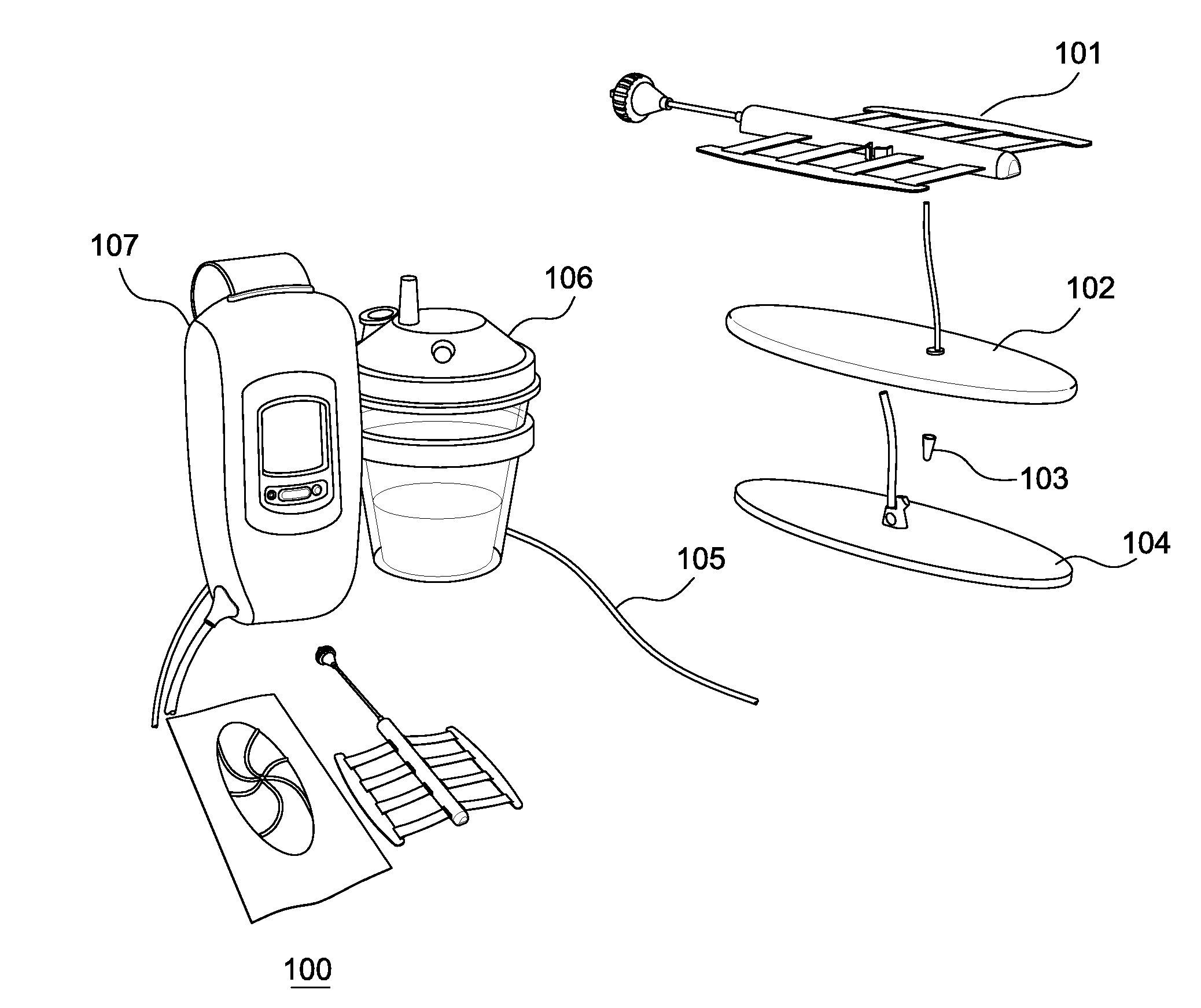
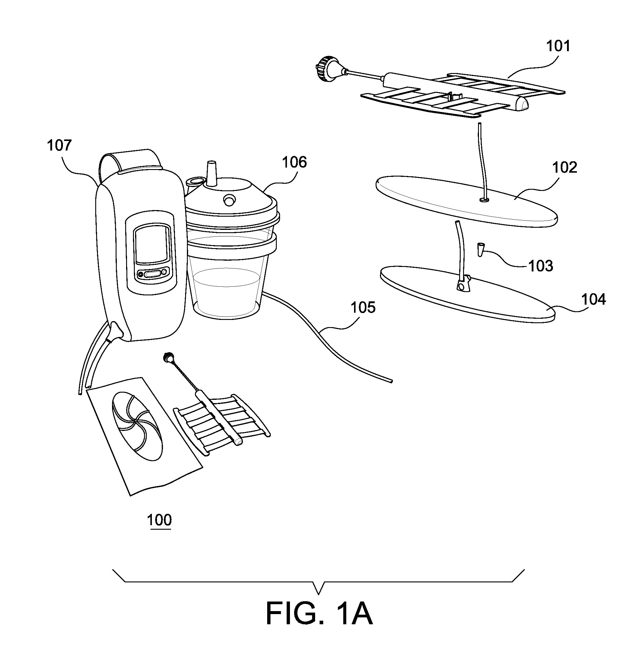
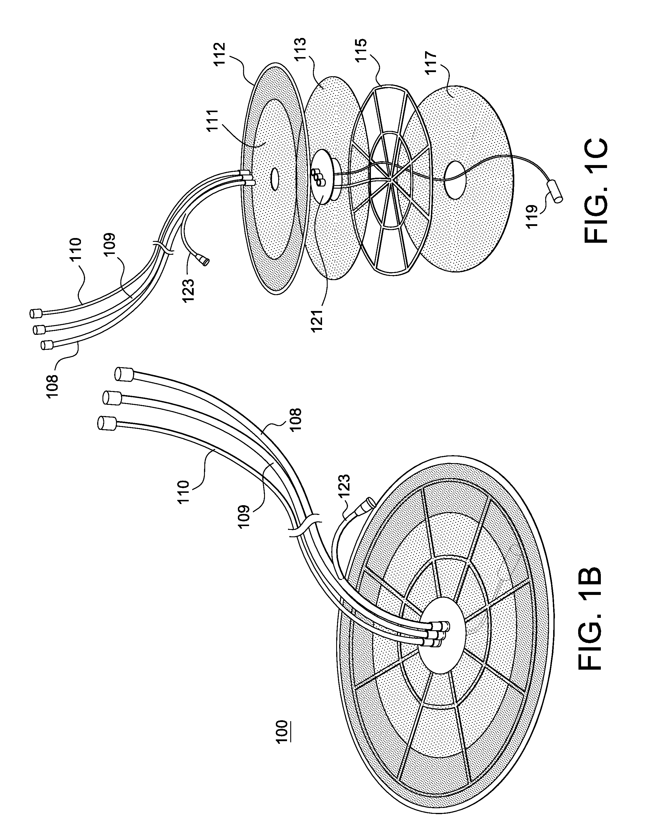
[0054]The present inventors recognized that the management of open wounds from trauma or disease, with the assistance of NPWT, benefits from the application of multiple features of the embodiments disclosed herein. From the time the wound is created it is beneficial if several interim activities occur prior to the final step in wound care, definitive soft tissue management. These interim activities include irrigation and debridement, minimization of microbial load, monitoring of the wound and sequential approximation of the wound—that is, closing of the wound—to the extent possible.

[0055]Typically, it is recognized that a wound care system cannot act completely independent of provider directed wound care. Surgical irrigation, gross wound decontamination, and debridement will remain the hallmarks of initial wound care in the foreseeable future. However, the present inventors recognized a number of improvements that aid in the development of a robust MWT integrated systems. Various em...


PUM

PropertyMeasurementUnit
Lengthaaaaaaaaaa
Lengthaaaaaaaaaa
Lengthaaaaaaaaaa

Abstract

A mechanical wound therapy (MWT) system includes a connection for a vacuum source, which is routed through an airtight covering to a porous material positioned over the wound. The porous material may be a tubing network interspaced by a netting material constructed of biologically inert or bioabsorbable material. Alternatively, the porous material may be a layered unified dressing in which layers of mesh, netting or thin perforated film are separated and fixedly attached to functional elements of the dressing (e.g., irrigation tubing) or spacers. The vacuum and irrigation systems may be completely separated. An airtight sealing layer or foldable adhesive sealing layer may seal the dressing and facilitate sealing the dressing to the wound margins. Additional modular devices such as a wound approximating system, positive pressure bladders and adjuvant therapy modules as well as enhanced monitoring technology can be added to synergistically increase the capabilities of each dressing.

Description

CROSS-REFERENCE TO RELATED APPLICATIONS[0001]The present application claims priority from, and incorporates by reference in their entireties, both U.S. provisional patent application 61 / 554,080 filed Nov. 1, 2011, and also U.S. provisional patent application 61 / 643,840 filed May 7, 2012.BACKGROUND[0002]1. Technical Field[0003]Various embodiments of the present invention relate to patient wound care, and more specifically, to systems and methods of wound coverings and dressings.[0004]2. Description of Related Art[0005]Since the mid-20th century various types of rudimentary vacuum-assisted devices have been used to facilitate coverage and closure of open wounds. Conventional vacuum-assisted wound care devices use a non-unified, piecemeal wound filling material sealed with an adhesive film, and a vacuum pump that maintains negative pressure on the wound while draining the effluent from the wound into a fluid collection canister.[0006]There is sometimes a need to modify the wound dressi...

Claims


Application Information

Patent Timeline
IPC IPC(8): A61N7/00A61M3/02A61M37/00A61N5/06A61F13/02A61F13/00
CPCA61F13/00063Y10T29/49826A61F13/0279A61M3/0283A61M37/00A61N5/0624A61N7/00A61M1/0084A61M1/0088A61M2205/15A61M2205/18A61M2205/3344A61M2205/3553A61M2205/3584A61M2205/3592A61M3/0279A61F13/023A61F2013/00536A61M1/0058A61B19/08A61F13/00068A61F13/0216A61B46/00A61M1/85A61M1/92A61M1/915A61M1/966A61M1/916A61M1/77A61M1/918A61F13/00A61F13/00021A61F13/00085A61F2013/00357
Inventor FREEDMAN, BRETTSHULER, MICHAEL
Owner J&M SHULER MEDICAL
Why Eureka
Try Eureka