
Automated functional diagnosis

a functional diagnosis and automatic technology, applied in the direction of instruments, heating types, static/dynamic balance measurement, etc., can solve the problems of inability to detect faults in hvac systems, complex and certain costs, so as to achieve cost-effective and efficient checking of hvac systems

Active Publication Date: 2014-03-06
BELIMO HOLDING AG
View PDF4 Cites 31 Cited by
  • Summary
  • Abstract
  • Description
  • Claims
  • Application Information

AI Technical Summary

Benefits of technology

This patent describes a method and system for checking the operation of an HVAC system. The invention uses an acoustic sensor to detect when the valve body is not properly closed, which can then be easily addressed. The system also measures fluid pressure to improve accuracy and reliability. By evaluating the measurement data and alerting when a malfunction is detected, the invention can automate maintenance and monitoring of the system, reducing costs and the need for excessive personnel expenditure. Overall, this patent provides a cost-effective and efficient way to check the performance of an HVAC system.

Problems solved by technology

Such tests may reveal whether flaps are functioning satisfactorily, built-in filters have to be replaced or there are leaks in the system.
The checking of HVAC systems is complex since various tests have to be carried out in situ by one or more inspectors in order to check the functional capability of the system.
As a result, to a certain extent considerable costs are incurred.
Faults in the HVAC system therefore cannot be detected until after a considerable time delay in some cases, as a result of which a safety risk or non-optimum operation of the HVAC system may remain undiscovered over a relatively long time.

Method used


Image

  • Automated functional diagnosis
  • Automated functional diagnosis

Examples


example 1

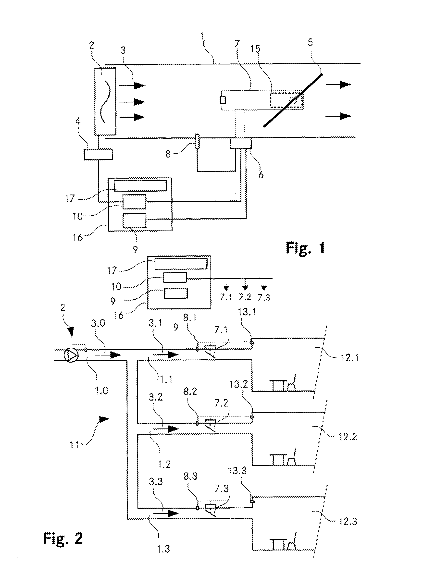
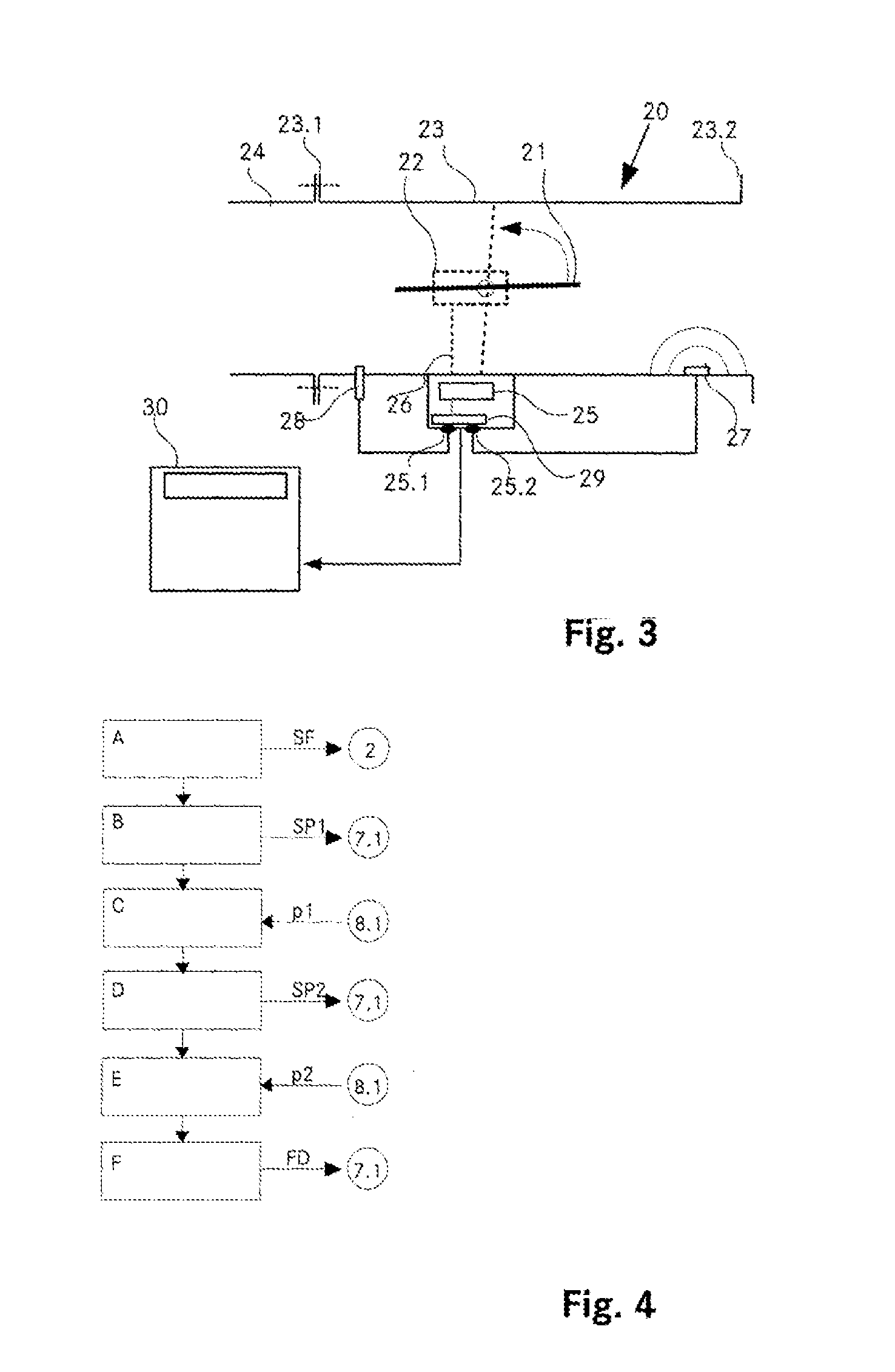
[0114]For the automated functional monitoring of the air flap 5, the control module 10 generates a control signal and transmits it to the drive controller 4 or the fluid flow drive 2 in order to set the fluid flow drive 2 to a specific power level and to make available a fluid flow 3.

[0115]The control module 10 then generates a first control signal and transmits it to the actuation module 6 in order to set the air flap 5 to a first setpoint position SP1. This first setpoint position is, for example, the entirely opened position of the air flap (valve body).

[0116]Subsequently, the fluid pressure of the fluid flow 3 is sensed by the fluid flow sensor 8 and stored as first fluid pressure p1 in the evaluation module 9.

[0117]In a subsequent step, a second control signal is transmitted to the actuation module 6 in order to move the air flap 5 into a second setpoint position SP2. This corresponds, for example, to the entirely closed position of the air flap.

[0118]After this, the fluid pres...

example 2

[0122]A particularly simple design for producing the functional diagnosis is that a single control signal is transmitted to the actuation module, which control signal corresponds to the closed position (setpoint position) of the valve body. Then, with a volume flow sensor it is measured whether the flow in the fluid flow duct 1 has come to a standstill. If this is the case, the evaluation module generates the functional diagnosis “functionally capable”. If the volume of flow is higher than a predefined limiting value, the functional diagnosis “faulty” is produced.

[0123]in addition, a third state of the functional diagnosis can be provided which categorizes the seal as still sufficient but critical. This state is referred to within the scope of the invention as “unclear”.

example 3

[0124]Instead of a first fluid pressure and a second fluid pressure, a series of fluid pressure values can be determined, wherein a fluid pressure of the fluid flow 3 is determined for each of a variety of settings of the fluid flow valve 7. As a result, the satisfactory method of functioning of the fluid flow valve 7 can be checked for a specific working range, or the entire working range, of the fluid flow valve 7. During the sensing of a series of flow pressure values, it is possible to dispense with a comparison with setpoint values and to determine the satisfactory functional state of the fluid flow valve 7 only from the increase or decrease in the fluid pressure difference between two adjacent fluid pressure values.


PUM


Abstract

The invention is based on an HVAC (heating, ventilation and air-conditioning) system which comprises the following components: a) a fluid flow duct (1), b) a fluid flow valve (7) which is arranged therein and has a valve body (5) in the fluid flow duct (1) and a valve motor (15) which moves the valve body (5), c) a control circuit for activating the valve motor, d) a sensor (8) in the fluid flow duct (1) and e) an evaluation module for evaluating signals of the sensor. In order to produce an automated functional control, the following procedure is adopted: f) a first actuation signal is preset for the valve motor by the control circuit, and the actuation signal corresponds to a first setpoint position of the valve body (5), g) registration of a first signal of the sensor (8) by the evaluation module, and h) determination of a functional diagnosis of the fluid flow valve on the basis of the first signal of the sensor.

Description

TECHNICAL BACKGROUND[0001]The invention relates to a method and to a system for the automated functional monitoring of an HVAC (heating, ventilation and air-conditioning) system which comprises the following components:[0002]a) a fluid flow duct (1),[0003]b) a fluid flow valve (5) which is arranged therein and has a valve body (5) in the fluid flow duct (1) and a valve motor (15) which moves the valve body (5),[0004]c) a control circuit for actuating the valve motor,[0005]d) a sensor in the fluid flow duct and[0006]e) an evaluation module for evaluating signals of the sensor.[0007]In addition, the invention relates to a fluid flow valve which can be used in an HVAC system.PRIOR ART[0008]There are regulations according to which the operator of an HVAC (heating, ventilation and air-conditioning) system must regularly check the method of functioning thereof. This is important, in particular, for safety components such as fire dampers. To do this, an inspector must check, for example ev...

Claims


Application Information

Patent Timeline
IPC IPC(8): F24F11/00
CPCF24F11/006F16K31/042F16K37/005F24F13/1426F16K37/0041F24F11/30F24F2110/30F24F2110/40F24F11/32F24F2140/40F24F11/62F24F11/74
Inventor LEHNERT, FRANKSCHMIDLIN, PETER
Owner BELIMO HOLDING AG
Learn More