Catalyst heating with exhaust back-pressure

a catalyst and back-pressure technology, applied in the direction of machines/engines, output power, electric control, etc., can solve the problems of limiting the temperature increase of exhaust, slipping emissions past the catalyst, unstable combustion, etc., to achieve the effect of reducing the temperature of exhaust gas traveling through the catalyst, and reducing the temperature of exhaust gas

Active Publication Date: 2014-03-13
FORD GLOBAL TECH LLC
View PDF12 Cites 17 Cited by
  • Summary
  • Abstract
  • Description
  • Claims
  • Application Information

AI Technical Summary

Benefits of technology

[0002]Catalysts positioned in the exhaust of engines act to convert emissions produced during combustion to compounds which may be released to the atmosphere. Frequently, these catalysts convert emissions most efficiently at elevated exhaust temperatures, and thus during engine cold start and warm-up conditions when the catalyst is below normal operating temperature, emissions may slip past the catalyst. One method to rapidly heat the catalyst includes increasing the temperature of exhaust gas traveling through the catalyst.

Problems solved by technology

Frequently, these catalysts convert emissions most efficiently at elevated exhaust temperatures, and thus during engine cold start and warm-up conditions when the catalyst is below normal operating temperature, emissions may slip past the catalyst.
However, the inventors herein have recognized a few issues with the above approach.
Increasing exhaust back-pressure by closing the exhaust back-pressure valve may increase the dilution of the cylinder charge with burned gases, resulting in unstable combustion under some conditions.
Further, the diluted cylinder charge may limit the amount of spark retard that can be applied, thus limiting the temperature increase of the exhaust.
The closure of the exhaust back-pressure valve may also be restricted to high-combustion stability operating conditions, such as low humidity and low altitude, to avoid increased combustion instability.
Further, by diagnosing the exhaust back-pressure system based on changes in designated operating conditions while the exhaust back-pressure valve moves, degradation of the system may be quickly detected, and if the system is degraded, additional mechanisms to heat the catalyst may be employed.

Method used


Image

  • Catalyst heating with exhaust back-pressure
  • Catalyst heating with exhaust back-pressure
  • Catalyst heating with exhaust back-pressure

Examples


Embodiment Construction

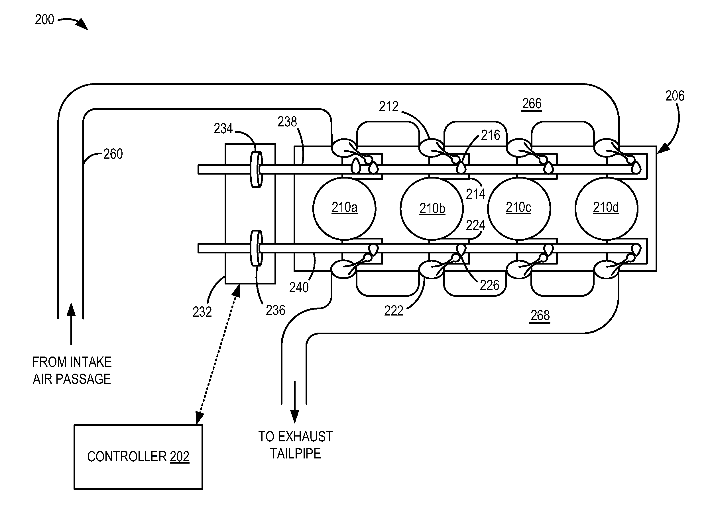
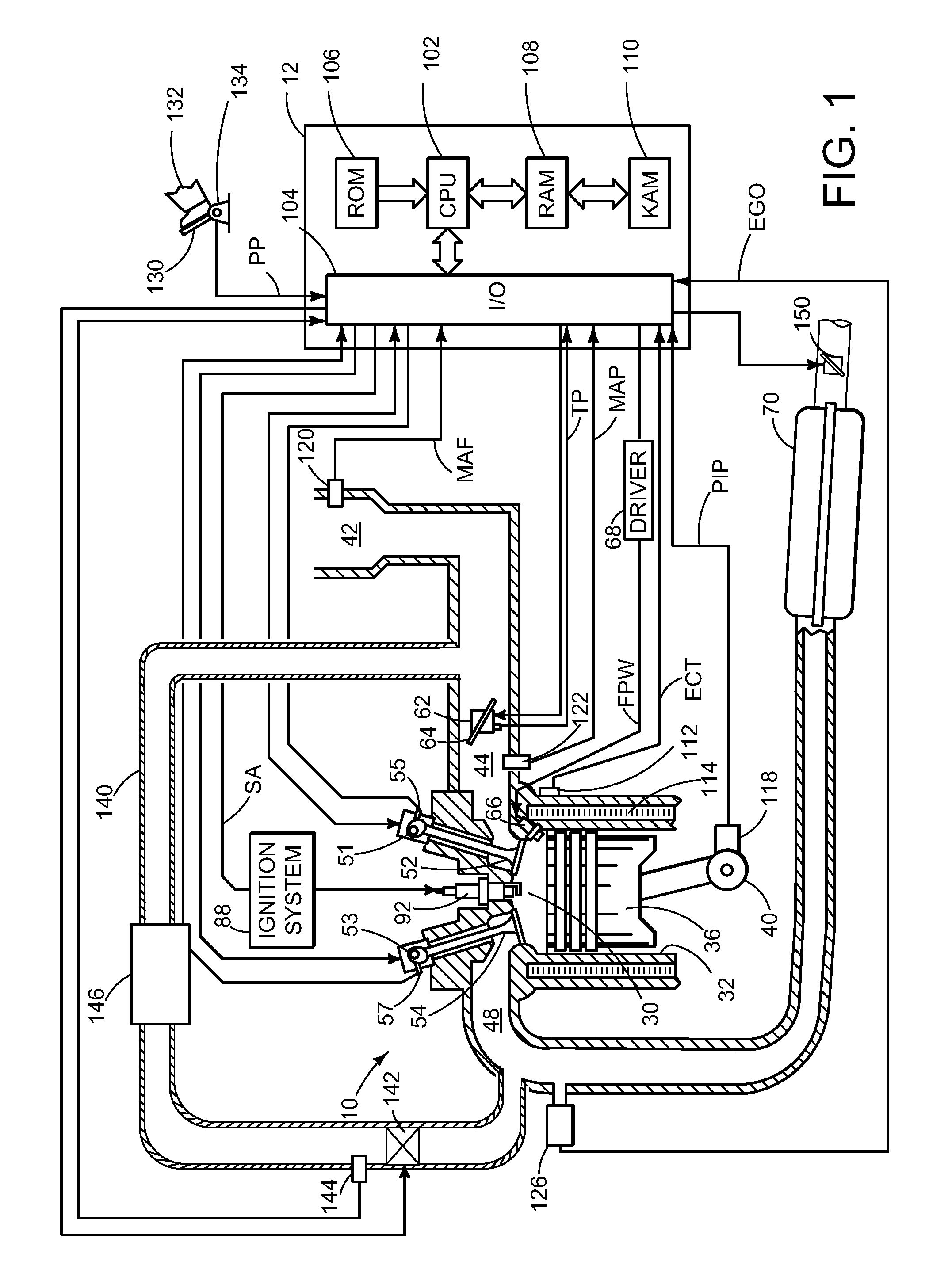
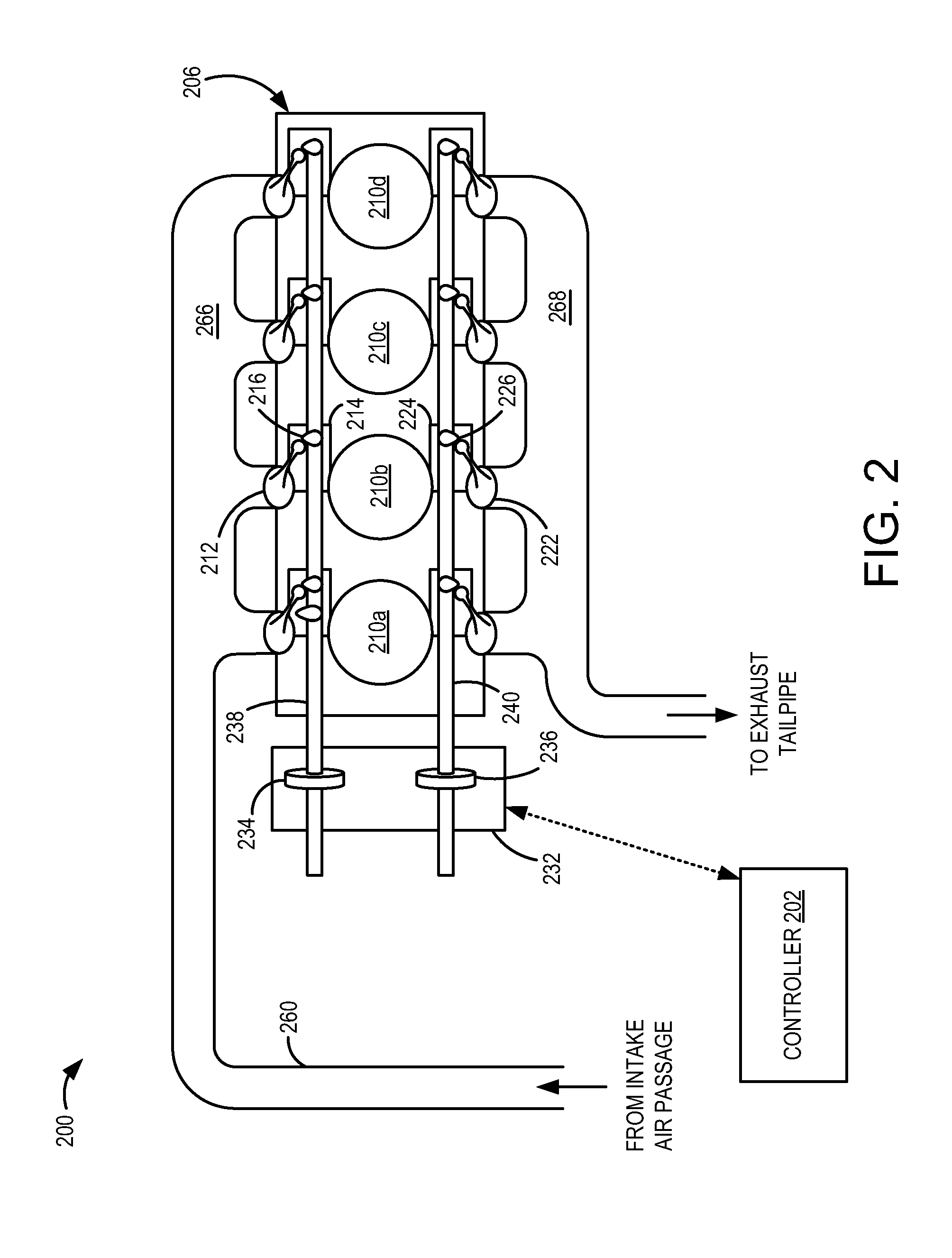
[0016]During an engine cold start, exhaust emissions may be released to the atmosphere before a catalyst positioned in the engine exhaust reaches operating temperature. One mechanism to rapidly heat the catalyst includes closing an exhaust back-pressure valve to throttle the exhaust, thus increasing the temperature of the exhaust passing through the catalyst. However, such throttling of the exhaust may increase the dilution of the charge in the cylinder with burned gases, thus degrading combustion stability and limiting the amount of spark retard that may be applied. To reduce the dilution of the cylinder charge, the closure of the exhaust back-pressure valve may be limited to conditions of high combustion stability, such as low humidity, low altitude, high volatility fuel, etc. Further, intake and exhaust valve overlap may be limited to reduce internal exhaust gas recirculation (EGR) and external EGR may be deactivated, thus limiting effective EGR. If indicated, the amount of spark...


PUM


Abstract

Embodiments for controlling an exhaust back-pressure valve are provided. In one example, a method for operating an engine comprises closing an exhaust back-pressure valve in response to a component temperature, adjusting intake and/or exhaust valve operation in response to closing the exhaust back-pressure valve to reduce cylinder internal exhaust gas recirculation (EGR), and while the exhaust back-pressure valve is closing, indicating degradation of an exhaust back-pressure system if a designated engine operating parameter remains constant. In this way, degradation of the exhaust back-pressure system may be diagnosed while maintaining combustion stability.

Description

FIELD[0001]The present disclosure relates to an internal combustion engine.BACKGROUND AND SUMMARY[0002]Catalysts positioned in the exhaust of engines act to convert emissions produced during combustion to compounds which may be released to the atmosphere. Frequently, these catalysts convert emissions most efficiently at elevated exhaust temperatures, and thus during engine cold start and warm-up conditions when the catalyst is below normal operating temperature, emissions may slip past the catalyst. One method to rapidly heat the catalyst includes increasing the temperature of exhaust gas traveling through the catalyst.[0003]One example approach for increasing exhaust gas temperature is described in U.S. Patent Application Publication 2010 / 0005784. In the cited reference, an exhaust back-pressure valve positioned in the exhaust of an engine is closed to increase the exhaust temperature in order to perform a desulfination of a catalyst.[0004]However, the inventors herein have recogni...

Claims


Application Information

Patent Timeline
Patent Type & Authority Applications(United States)
IPC IPC(8): F02D41/06F02P5/00
CPCF02D9/04F02D13/0207F02D13/0219F02D13/0265F02D41/006F02D41/0245F02D41/0255F02D41/221F02D2041/001F02D2200/0404F02D2200/0406F02D2200/0802F02D2250/34F02M26/01F02M26/23F02M26/10Y02T10/12Y02T10/40F02D13/0242
Inventor LEONE, THOMAS G.MOILANEN, PETER C.
Owner FORD GLOBAL TECH LLC
Why Eureka
Try Eureka