Centrifugal precipitator for precipitating oil mist from the crankcase ventilation gas from an internal combustion engine

a technology of internal combustion engine and ventilation gas, which is applied in the direction of centrifuges, machines/engines, separation processes, etc., can solve the problems of high cost, high manufacturing cost, and relative heavy weight of housings made of a plurality of metal parts, and achieves advantageously light weight, lower cost, and high mechanical load

Active Publication Date: 2014-03-13
HENGST WALTER
View PDF7 Cites 9 Cited by
  • Summary
  • Abstract
  • Description
  • Claims
  • Application Information

AI Technical Summary

Benefits of technology

[0020]Finally, the present invention proposes for the centrifugal precipitator a crankcase pressure regulating valve that is situated in the run of the pure gas outlet and is connected to the housing or built into the housing. In this way, with small outlay of constructive space and assembly, a further function necessary for the operation of the associated internal combustion engine can be integrated into the centrifugal precipitator.
[0021]As mentioned above, the main element and the housing floor are individual parts that can be manufactured separately, offering the advantageous possibility of producing each component from a separate functionally appropriate material. The main element is usefully made of a more stable material, such as metal, so that it can accept higher mechanical loads resulting in particular from the rotation of the rotor with a high rotational speed and from the clamping against the counterflange. The housing floor is not subject to these mechanical loads, so that it can be made, without disadvantages, of a plastic that is less stable but is advantageously lighter and lower in cost. At the same time, the plastic material offers the advantage that the housing floor inherently has a certain movability that is useful for compensating dimensional tolerances during the connection of the housing floor to the main element on the one hand and to the counterflange on the other.
[0022]Particularly preferably, the main element is a pressure die-cast part made of light metal, in particular aluminum. In this embodiment, the main element is on the one hand capable of accepting mechanical loading, but on the other hand is nonetheless relatively low in weight and is capable of being produced at very low cost as a mass-produced part.
[0023]Particularly preferably, the housing floor is an injection-molded part made of thermoplastic, in particular polyamide (PA). This material is well suited for the mechanical and thermal loads that occur, and has low weight and advantageous material costs. Advantageously, in plastic injection molding the housing floor, with all necessary connections, can be produced in one piece off-tool, i.e. without post-processing. In this way, a low-cost production of the housing floor as a mass-produced part is also possible.
[0024]In addition, through the production of various housing floors and through the installation of the various housing floors on identical main elements, different embodiments of the centrifugal precipitator having different connections can be realized with a low outlay, thus making available an advantageous modular system.

Problems solved by technology

In this known centrifugal precipitator, it is regarded as disadvantageous that it has a relatively heavy weight, because in order to achieve the necessary mechanical stability its housing is made up to the largest possible extent of metal, in particular aluminum.
Such a housing made of a plurality of metal parts is relatively expensive to manufacture, in particular if various connection interfaces, such as connecting pieces and flanges, are present in and on the housing, which have to be processed separately by machining, which is expensive.

Method used


Image

  • Centrifugal precipitator for precipitating oil mist from the crankcase ventilation gas from an internal combustion engine
  • Centrifugal precipitator for precipitating oil mist from the crankcase ventilation gas from an internal combustion engine
  • Centrifugal precipitator for precipitating oil mist from the crankcase ventilation gas from an internal combustion engine

Examples


Embodiment Construction

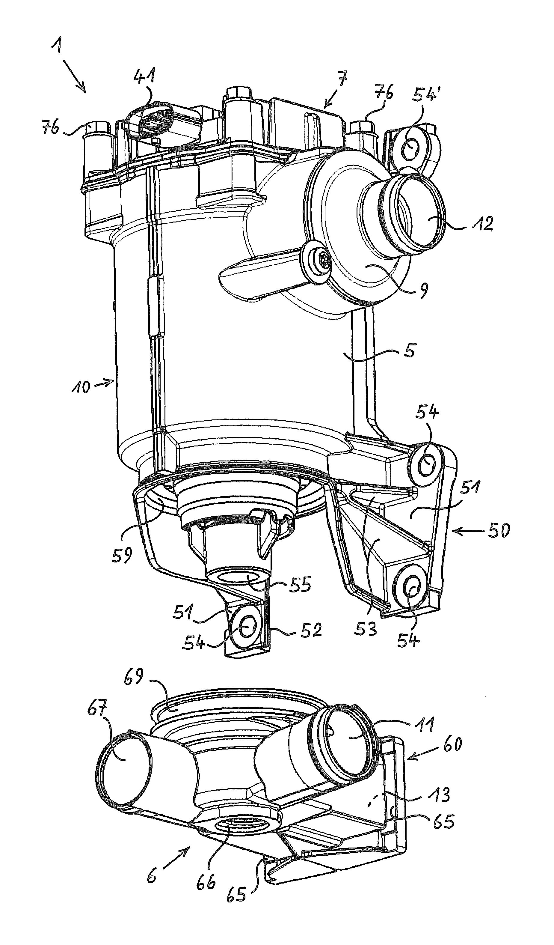
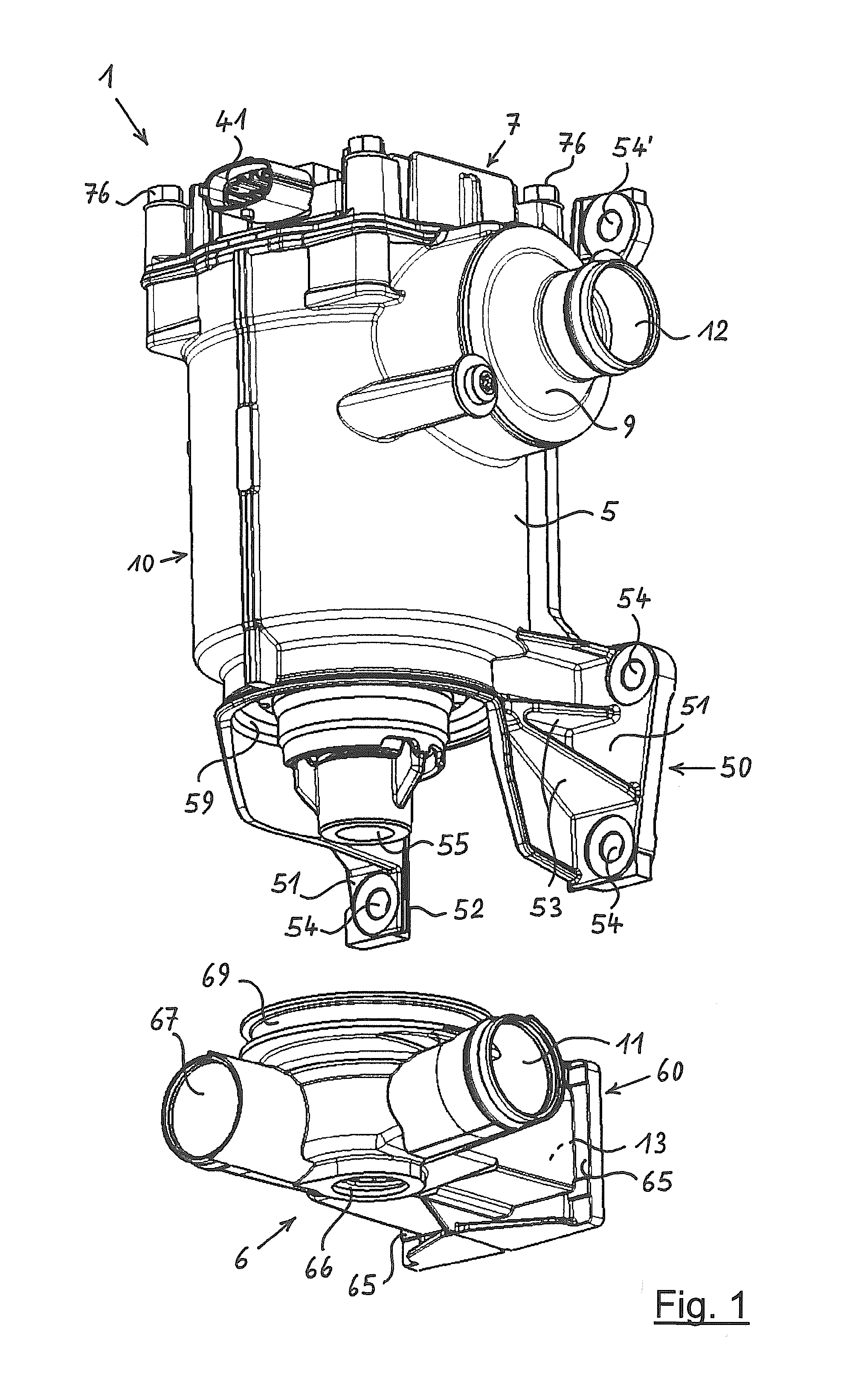
[0031]The upper part of FIG. 1 of the drawing shows, in a perspective view, a centrifugal precipitator 1 having a housing 10, and the lower part of the Figure shows an associated housing floor 6 not yet connected to the rest of centrifugal precipitator 1.

[0032]Centrifugal precipitator 1 has housing 10, which forms a main element 5 of precipitator 1. At the upper side, housing 10 is sealed by a cover 7 that is detachably connected to housing 10 by screws 76. Cover 7 here forms a cooling element for an electric drive of a centrifugal rotor (not visible here) situated in the interior of housing 10. For the supply of electric energy, cover 7 has, on its side facing the observer, a power connection 41, here in the form of a connecting socket.

[0033]At the side of housing 10 pointing to the right, there is situated a crankcase pressure regulating valve 9 whose housing is made at least partly integrally with housing 10 of centrifugal precipitator 1. On crankcase housing pressure regulating ...


PUM

PropertyMeasurementUnit
circumferenceaaaaaaaaaa
shapeaaaaaaaaaa
structureaaaaaaaaaa

Abstract

A centrifugal precipitator having a housing and a rotatable driven rotor for precipitating oil mist from crankcase ventilation gas of an internal combustion engine. The housing has an inlet for gas to be deoiled, a deoiled gas outlet and an oil outlet. The housing includes a metallic main element surrounding the rotor and carrying the rotor bearing. A housing bottom is built onto the main element from below. The housing attaches with a flange to a counterflange or module of the engine. The housing flange is formed on the main element and the housing. The oil outlet runs through a first flange part of the housing bottom and this flange part has a circumferential rim. A second flange part of the main element has a collar engaging over part of its periphery behind the rim and can be clamped with the rim in between against the counterflange.

Description

CROSS-REFERENCES TO RELATED APPLICATIONS[0001]This application claims the benefit of the German patent application No. 10 2011 076 465.8 filed on May 25, 2011, the entire disclosures of which are incorporated herein by way of reference.BACKGROUND OF THE INVENTION[0002]The present invention relates to a centrifugal precipitator for precipitating oil mist from the crankcase ventilation gas of an internal combustion engine, the centrifugal precipitator having a housing, a drivable rotor mounted rotatably therein, and a rotational drive for the rotor, the housing having a crude gas inlet for crankcase ventilation gas that is to be deoiled, a pure gas outlet for deoiled crankcase ventilation gas, and an oil outlet for oil precipitated from the crankcase ventilation gas, the housing having a multipart construction with a main element that surrounds the rotor and that holds the bearing thereof, having a housing cover containing the rotational drive, and having a housing floor built onto th...

Claims


Application Information

Patent Timeline
Patent Type & Authority Applications(United States)
IPC IPC(8): F02M25/06
CPCF02M25/06B01D45/14B04B5/005B04B5/12B04B7/02F01M2013/0422
Inventor ROELVER, MARTIN
Owner HENGST WALTER
Why Eureka
Try Eureka