3D short range detection with phased array radar

Inactive Publication Date: 2014-03-13
TOYOTA MOTOR ENGINEERING & MANUFACTURING NORTH AMERICA
View PDF3 Cites 63 Cited by
  • Summary
  • Abstract
  • Description
  • Claims
  • Application Information

AI Technical Summary

Benefits of technology

[0010]At least one phase shifter from the transmitting portion of the radar microchip is connected to each individual cell of the transmitting line of antenna cells and affords for the radar microchip to control the radar beam in the horizontal direction. Likewise, at least one phase shifter from the receiving portion of the radar microchip is connected to each individual cell of the receiving line of antenna cells and affords the radar microchip to control the radar beam in the vertical direction.
[0011]Controll

Problems solved by technology

These systems are limited to 2D scans in a single plane due to cost and practicality.
Conventional 2D radar systems are often only able to provide information on an object's range and azimuth.
Many of these systems scan in a horizontal direction about the front of the automobile and as such the systems do not have vertical resolution.
The system scans with a fixed vertical window and cannot distinguish between objects on the road surface and those suspended above the road surface.
Due to the planar nature of the scan, in a practical application the radar system's algorit

Method used


Image

  • 3D short range detection with phased array radar
  • 3D short range detection with phased array radar
  • 3D short range detection with phased array radar

Examples


Embodiment Construction

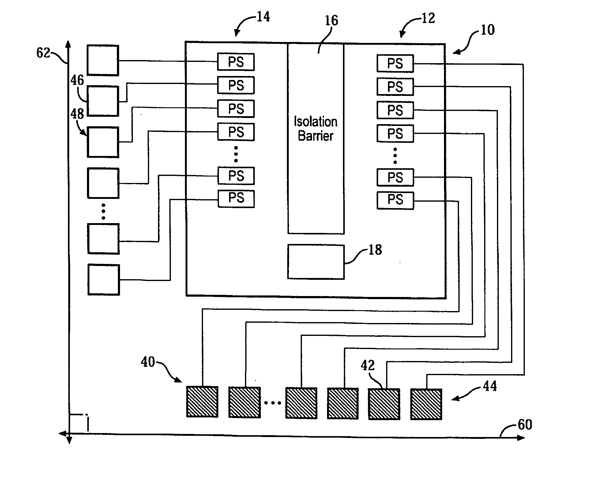
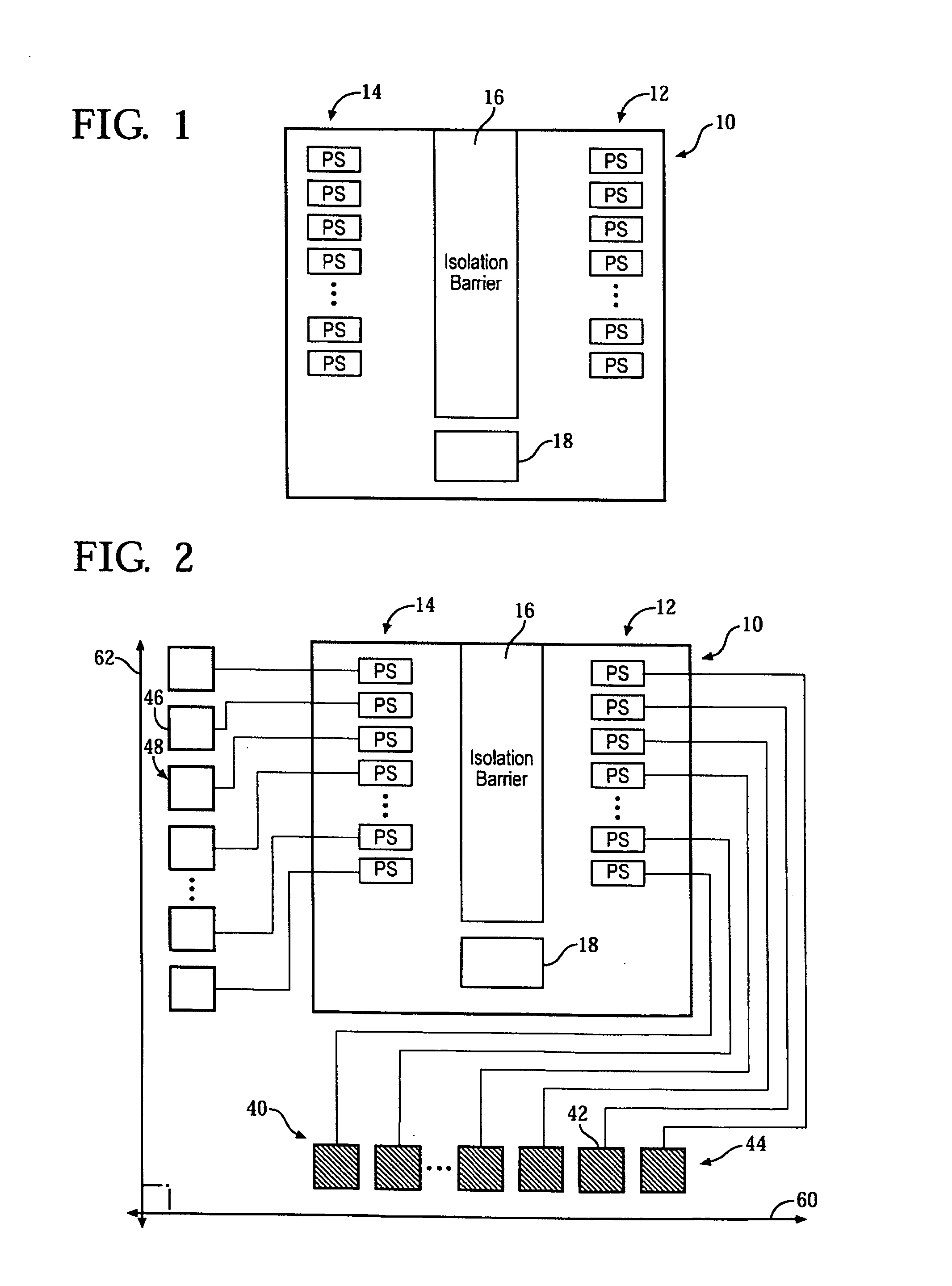
[0018]A microchip for transmitting and receiving radar signals is provided. The microchip can have a plurality of receiving phase shifters and a plurality of transmitting phase shifters. In addition, the microchip can have a plurality of transmitting antenna cells along a first axis and a plurality of receiving antenna cells along a second axis. In some instances, the second axis is orthogonal to the first axis. At least one of the transmitting phase shifters can be linked to each of the transmitting antenna cells and at least one of the receiving phase shifters can be linked to each of the receiving antenna cells.

[0019]An isolation barrier can be present on the microchip and separate the transmitting phase shifters from the receiving phase shifters. The isolation barrier can be constructed by a series of vertical interconnect accesses (vias) through all layers of a multilayer microchip and connect the layers to a ground layer.

[0020]The receiving phase shifters can be grouped as a r...


PUM


Abstract

A radar microchip for short range detection with phased array radar uses phase shifters along with an antenna array to steer the transmitted and received radar beams along orthogonal axes to achieve a 3D scan. Individual phase shifters connected to antenna cells that transmit and receive the radar beams steer the radar along two orthogonal axes by controlling the phase of the radar. The radar then detects where the two beams overlap. The antenna cells are further aligned along these orthogonal axes. An isolation barrier between the phase shifters of the transmitted and received signals reduces cross coupling on the radar microchip.

Description

FIELD OF THE INVENTION[0001]The invention relates to a radar microchip for detecting objects and, more specifically, a radar microchip used in automobiles to improve target classification of threatening and non-threatening objects.BACKGROUND OF THE INVENTION[0002]Radar systems are often used on automobiles to provide information about the area surrounding the automobile to a vehicle system such as an adaptive cruise control, various control systems and the like. Basic radar systems generally contain a transmitting antenna array, a receiving antenna array and associated hardware necessary to process the signals. As integrated circuit technology has advanced, the size and cost of such components has decreased to the point where radar systems can be contained on a single microchip and have become commonplace on automobiles.[0003]The majority of current commercial automotive radar systems scan in two dimensions (2D). These systems are limited to 2D scans in a single plane due to cost an...

Claims


Application Information

Patent Timeline
IPC IPC(8): H01Q3/30
CPCH01Q3/30G01S7/032H01Q1/3233
Inventor SCHMALENBERG, PAUL DONALDLEE, JAE SEUNGSHIOZAKI, KOJI
Owner TOYOTA MOTOR ENGINEERING & MANUFACTURING NORTH AMERICA
Why Eureka
Try Eureka