Injection molding machine with Anti-vibration structure for electric power panel

Active Publication Date: 2014-03-13
FANUC LTD
View PDF12 Cites 2 Cited by
  • Summary
  • Abstract
  • Description
  • Claims
  • Application Information

AI Technical Summary

Benefits of technology

[0016]According to the present invention, there may be provided an electric power panel, comprising a vibration absorber for reducing adverse effects of vibration or shock on the electric power panel

Problems solved by technology

If mold opening/closing operation or resin injection operation is quickly performed with high response, therefore, vibration occurs in a mold opening/closing direction.
Since the vibration absorbing material is disposed just below the electric power panel, however, it cannot be easily replaced if it is degraded and broken.
In the electrical components, including the controller and control circuits, mounted on the electric power panel, cracking of solder

Method used


Image

  • Injection molding machine with Anti-vibration structure for electric power panel
  • Injection molding machine with Anti-vibration structure for electric power panel
  • Injection molding machine with Anti-vibration structure for electric power panel

Examples


Example

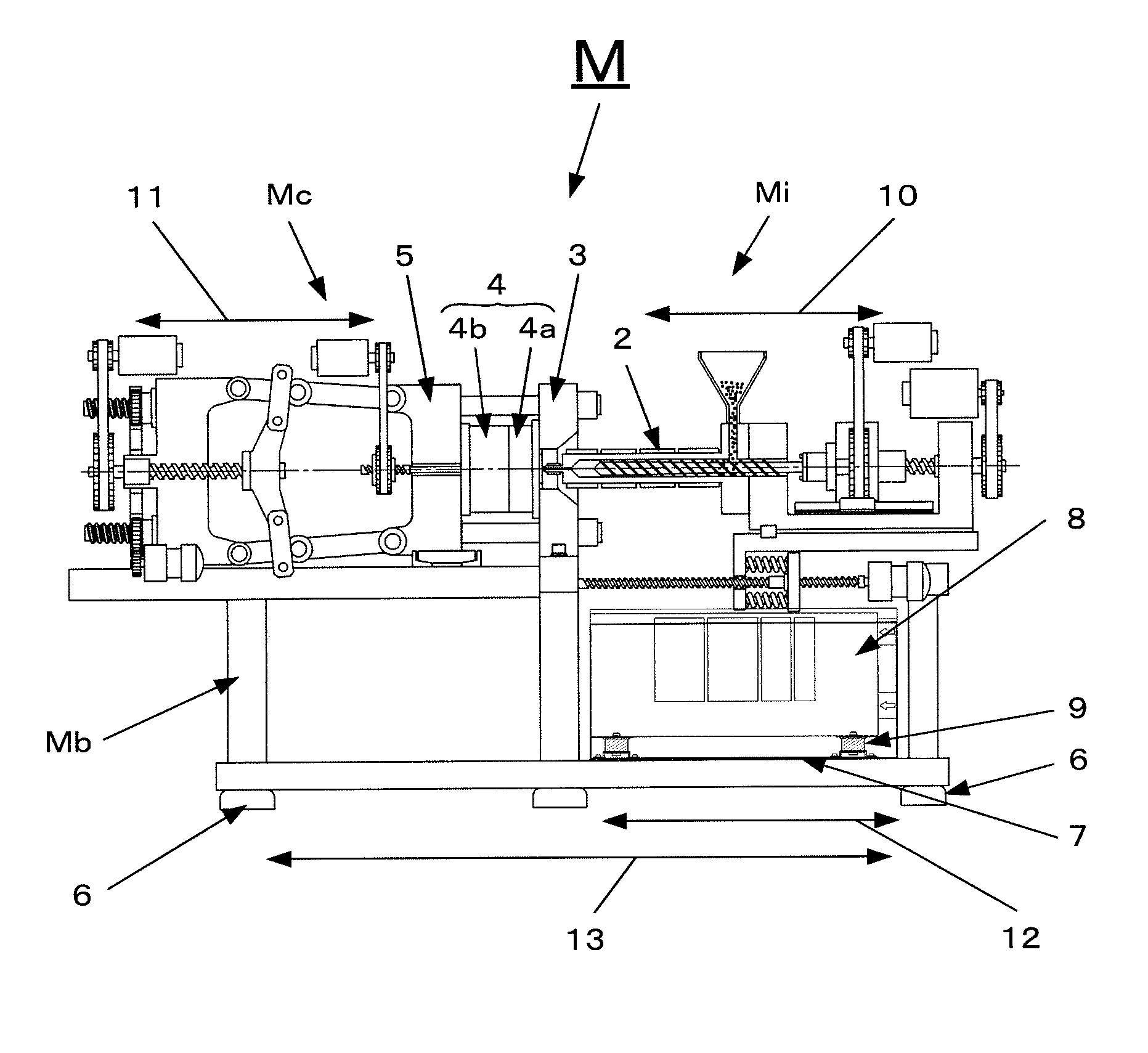
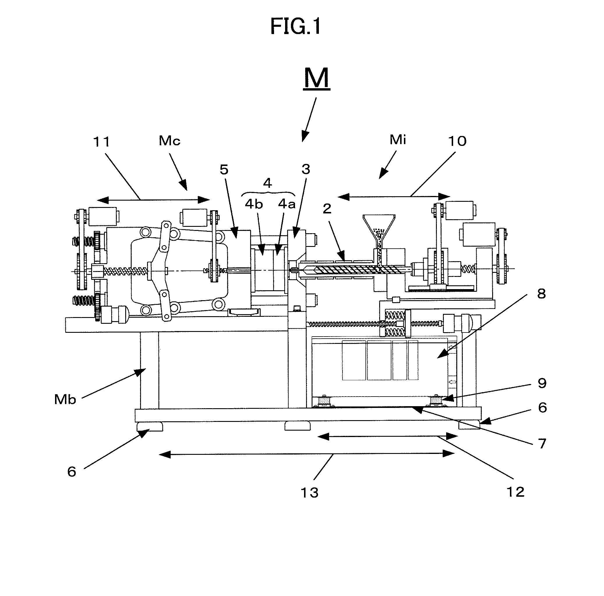
[0029]One embodiment of an injection molding machine according to the present invention will be described with reference to FIG. 1.

[0030]An injection molding machine M is of a horizontal type, in which an injection mechanism section Mi and a mold clamping mechanism section Mc are mounted on a base Mb. A molten resin is injected from an injection cylinder 2 of the injection mechanism section Mi into a cavity, which is formed by bringing a stationary mold half 4a attached to a stationary platen 3 of the mold clamping mechanism section Mc and a movable mold half 4b attached to a movable platen 5 into close contact with each other.

[0031]In performing a molding cycle, the injection molding machine M is subjected to vibration or shock (vibration of mold clamping operation designated by numeral 11) generated during mold clamping operation (reciprocation of the movable platen 5) and vibration or shock (vibration of injection operation designated by numeral 10) generated during injection ope...


PUM

PropertyMeasurementUnit
Widthaaaaaaaaaa

Abstract

An electric power panel used in an injection molding machine is formed of a box-like member mounted with an electrical component. An electric power panel mounting member secured to a bottom portion of the electric power panel is attached to a floorboard by means of a vibration absorber. The electric power panel mounting member has a width greater than a width of the box-like member in a depth direction, and the vibration absorber is disposed on either end portion of the electric power panel mounting member outside the box-like member.

Description

BACKGROUND OF THE INVENTION[0001]1. Field of the Invention[0002]The present invention relates to an injection molding machine, and more particularly, to an injection molding machine provided with an anti-vibration structure for an electric power panel.[0003]2. Description of the Related Art[0004]As shown in FIG. 11, an injection molding machine M has such a structure that a mold clamping mechanism section Mc and an injection mechanism section Mi are mounted on a base Mb and an electric power panel is accommodated in the base Mb. The electric power panel accommodated and secured in the base Mb is mounted with electrical components, such as a controller and control circuit of the injection molding machine M.[0005]The injection molding machine M is designed to mass-produce molded products and requires reduction of the molding cycle time to improve productivity. In general, the cycle time is reduced by increasing the speed of a motor to achieve high acceleration-deceleration response. I...

Claims


Application Information

Patent Timeline
IPC IPC(8): B29C45/17
CPCB29C45/1774B29C45/1761B29C2045/1767B29C2045/1797
Inventor URUSHIZAKI, TETSUHARUKOYAMA, HIDEKI
Owner FANUC LTD
Why Eureka
Try Eureka