Pressing Of Transformer Windings During Active Part Drying

a technology of windings and transformers, which is applied in the direction of magnetic bodies, manufacturing tools, magnetic core manufacture, etc., can solve the problems of short lead time in production, achieve the effect of facilitating maintenance of clamping force, less space in the transformer, and careful control of vertical adjustment of windings

Inactive Publication Date: 2014-03-20
ABB RES LTD
View PDF9 Cites 6 Cited by
  • Summary
  • Abstract
  • Description
  • Claims
  • Application Information

AI Technical Summary

Benefits of technology

[0010]A further advantage is that an individual pressing force is applied to the winding assembled onto the respective transformer core limb. In case the windings are different in length, different pressing forces can be applied to the respective winding.
[0011]In an embodiment of the present invention, a set of windings is assembled on the respective transformer limb. An advantage related to the pressing of a set of windings where each winding set is assembled onto a respective limb of the transformer core, is that the same clamping pressure is applied to the respective winding set. Where pressing force is applied to a plurality of winding sets, the pressing force is typically applied simultaneously to all the winding sets.
[0012]In an embodiment of the present invention, wedging is performed after the transformer active part has been dried. To this end, insulation material is inserted between the windings and a transformer core clamp such that compacting of the windings can be maintained when the applied pressing force on the windings is released after the transformer active part drying is completed. The wedging performed in this embodiment facilitates maintenance of the clamping force on the windings when the force from the pressure applying means is released.
[0013]In a further embodiment of the present invention, the pressure applying means are hydraulic jacks. The hydraulic jacks advantageously allow a very exact control of the pressure applied.
[0014]In yet another embodiment of the present

Problems solved by technology

This will subsequently lead to s

Method used


Image

  • Pressing Of Transformer Windings During Active Part Drying
  • Pressing Of Transformer Windings During Active Part Drying
  • Pressing Of Transformer Windings During Active Part Drying

Examples


Embodiment Construction

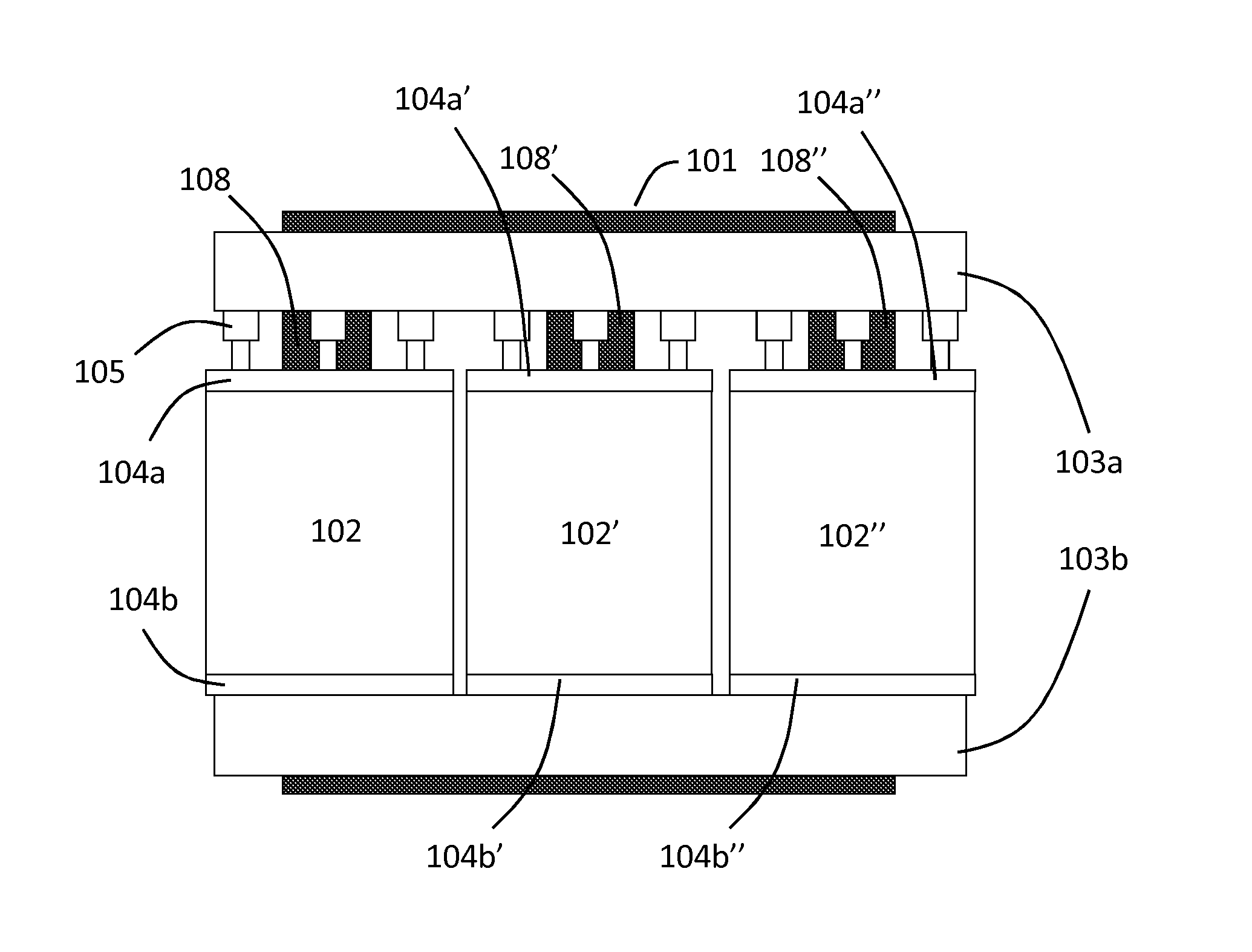
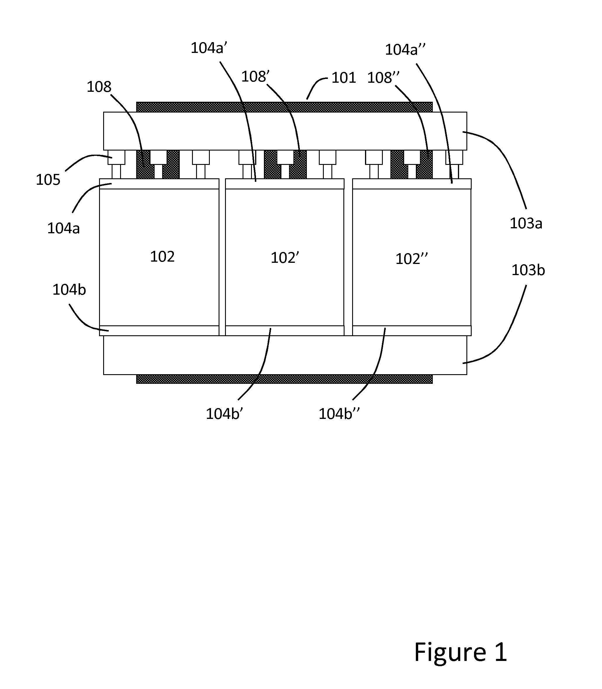
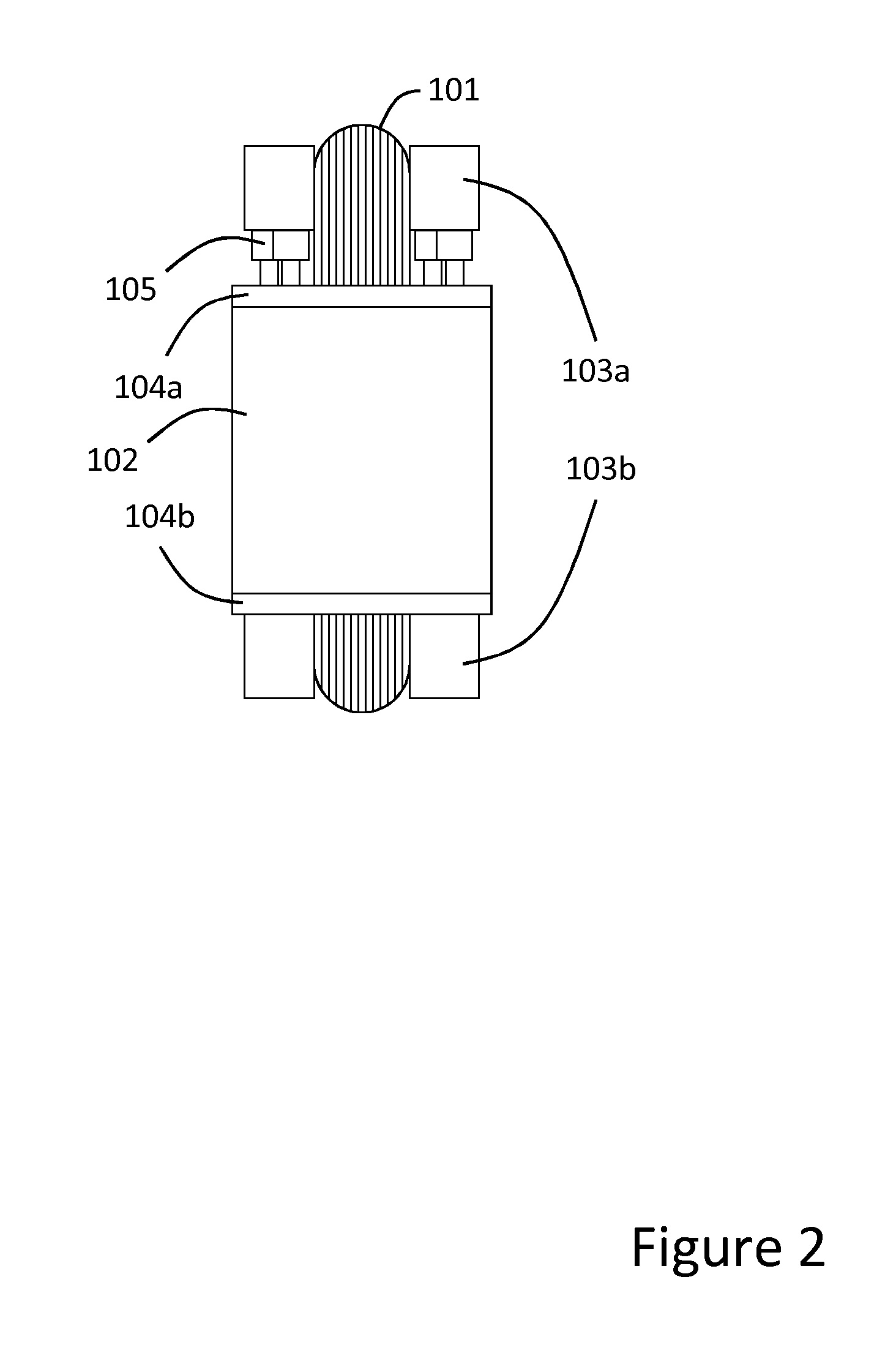
[0024]FIG. 1 illustrates pressing of an active part of a transformer, i.e. the pressing of windings mounted onto a transformer core, according to an embodiment of the present invention. FIG. 1 shows a three-phase transformer core 101 thus having three limbs 108, 108′, 108″ with a set of windings 102, 102′, 102″ concentrically mounted on each limb. Further, upper 103a and lower 103b core clamps are mounted on the core to stabilize and keep the core together. The core clamps are further used to assist in applying an individual clamping force on the respective winding set 102, 102′, 102″. Upper and lower press plates 104a, 104a′, 104a″ and 104b, 104b′, 104b″, respectively, are arranged to apply an individual pressing force on the respective winding sets during drying of the active part of the transformer, and to control the clamping force applied on the winding sets 102, 102′, 102″ after drying when the transformer is to be transported as well as when the transformer is in operation. T...


PUM

PropertyMeasurementUnit
Forceaaaaaaaaaa
Pressureaaaaaaaaaa

Abstract

A method and arrangement for pressing of windings assembled onto a transformer. The method includes applying pressing force on the windings, and controlling the pressing force on the windings during drying of transformer active part. Thus, before the drying process commences, the windings are assembled onto the transformer core and a pressing force is applied to the windings assembled onto a respective transformer core limb, wherein an individual pressing force is applied to the respective winding. This individual pressing force applied to the respective winding is then controlled during the process of drying the transformer active part. The windings will as a result advantageously be effectively compressed onto the core and stabilized.

Description

FIELD OF THE INVENTION[0001]The present invention generally relates to a method and arrangement of pressing of windings assembled onto a transformer.BACKGROUND OF THE INVENTION[0002]It is important that transformer windings are well-clamped and robust during transport to site and subsequent operation. To obtain this, the windings are compressed axially and clamped in position on the transformer core after drying the transformer active part. Drying is undertaken since cellulose insulation of the winding must be free from moisture. Moisture in the insulation of the windings deteriorates transformer operation; first of all, the dimensions of the cellulose-clad windings change as moisture leaves the cellulose material. Second, the material may partly lose its insulating effect with subsequent electrical problems in the transformer.[0003]However, notwithstanding transformer active part drying, the clamping force of the press plates applied to the windings is reduced with time because of ...

Claims


Application Information

Patent Timeline
IPC IPC(8): H01F41/02
CPCH01F41/0206H01F27/002H01F27/306Y10T29/5313Y10T29/49073
Inventor ANGER, JANGAFVERT, UNOGIRLANDA, ORLANDOGOERANSSON, DAVIDCABRAJIC, ZDENKO
Owner ABB RES LTD
Why Eureka
Try Eureka