Relative rotational angular displacement detection device, torque detection device, torque control device, and vehicle

a technology of relative rotation and angular displacement, which is applied in the direction of electric variable regulation, process and machine control, instruments, etc., can solve the problems of high production cost and assembly cost of detection devices, and achieve high degree of accuracy, high accuracy assembling, and simple structure

Inactive Publication Date: 2014-03-20
YAMAHA MOTOR CO LTD
View PDF0 Cites 9 Cited by
  • Summary
  • Abstract
  • Description
  • Claims
  • Application Information

AI Technical Summary

Benefits of technology

[0037]According to some preferred embodiments of the present invention, the permanent magnet is attached to one of the pair of rotatable members in such a manner that magnetic poles are arranged so as to change in polarity alternately in the circumferential direction of the axis of rotation, and the ring body of the magnetic flux inducing ring is attached to the other of the pair of rotatable members so that a plurality of protrusions protruding from the ring body are arranged at positions facing the magnetic pole of the permanent magnet. Therefore, the protrusion of the magnetic flux inducing ring can be formed into a simple shape, which in turn can form the protrusion with a high degree of accuracy. Furthermore, since the protrusions of the magnetic flux inducing ring are arranged at positions facing the magnetic poles in the magnetization direction of the permanent magnet, the relative position of the protrusion with respect to the permanent magnet can be determined only by the distance in the axial direction, which enables high accuracy assembling. Therefore, although the relative rotational angular displacement detection device is simple in structure and simple in assembly, the relative rotational angular displacement of the pair of rotatable members which are relatively rotatable can be detected with a high degree of accuracy.
[0038]In the relative rotational angular displacement detection device, the magnetic flux of the ring body of the magnetic flux inducing ring magnetized depending on the relative position of each protrusion of the magnetic flux inducing ring and each magnetic pole of the permanent magnet is detected by the magnetic detection portion. This reduces the number of component parts and simplifies the structure. Since the structure is simple, the production and assembly can also be performed easily with a high degree of accuracy.
[0039]The magnetic detection portion includes a first facing portion arranged to face a part of the ring body to induce a magnetic flux of a part of the ring body, a second facing portion arranged at a position apart from the first facing portion in a circumferential direction of the axis of rotation to induce a magnetic flux of a part of the ring body, a first magnetic sensor configured to detect the magnetic flux induced by the first facing portion, and a second magnetic sensor configured to detect the magnetic flux induced by the second facing portion. This reduces the number of component parts and simplifies the structure. Since the structure is simple, the production and assembly can also be performed easily with a high degree of accuracy.
[0040]Further, the first facing portion and the second facing portion are fixed in the circumferential direction of the axis of rotation regardless that the permanent magnet and the magnetic flux inducing ring rotate about the axis of rotation. Therefore, the magnetic sensors can be arranged on a non-rotatable side such as a vehicle body, which simplifies the mounting structure and reduced the risk of malfunctions.
[0041]By arranging the first facing portion and the second facing portion at positions where a central angle of the first facing portion and the second facing portion satisfies a relational expression of [an electric angle of the permanent magnet×N+the electric angle / 2, where N is a positive integers], or in cases where the magnetic detection portion includes M pieces of facing portions includes the first facing portion and the second facing portion, by arranging the facing portions at positions where a central angle of adjacent facing portions satisfies a relational expression of [an electric angle of the permanent magnet×N+the electric angle / (2+M), where N and M are positive integers], in cases where the first and second magnetic sensors are relatively rotated in the circumferential direction with respect to the ring body of the magnetic flux inducing ring in a state in which the magnetic flux inducing ring and the permanent magnet are not relatively rotated, i.e., in a state in which no or less fluctuation of the output from the magnetic detection portion can be expected since the pair of rotatable members are not relatively displaced, when the outputs of both the magnetic sensors are combined, the amplitude of the combined output waveform is reduced as compared with the amplitude of the output waveform of each magnetic sensor. Thus, the output fluctuations from the magnetic sensor portion which may cause erroneous detection can be reduced, resulting in improved detection accuracy.

Problems solved by technology

However, since both members are formed into an annular shape, respectively, and the accuracy of the gap is secured, the production cost and the assembly cost of the detection device was high.

Method used


Image

  • Relative rotational angular displacement detection device, torque detection device, torque control device, and vehicle
  • Relative rotational angular displacement detection device, torque detection device, torque control device, and vehicle
  • Relative rotational angular displacement detection device, torque detection device, torque control device, and vehicle

Examples


Embodiment Construction

[0062]In the following paragraphs, some preferred embodiments of the present invention will be described with reference to the attached drawings by way of example and not limitation. It should be understood based on this disclosure that various other modifications can be made by those in the art based on these illustrated embodiments.

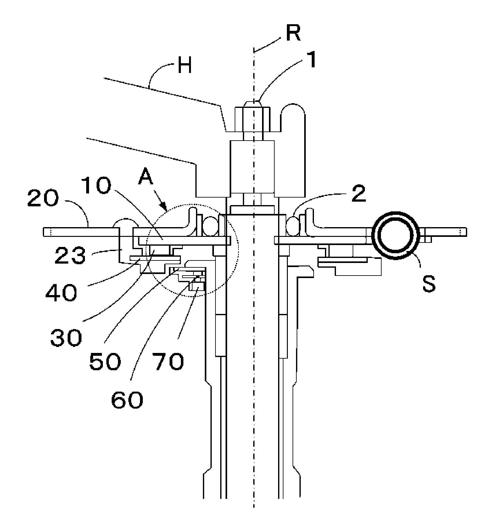
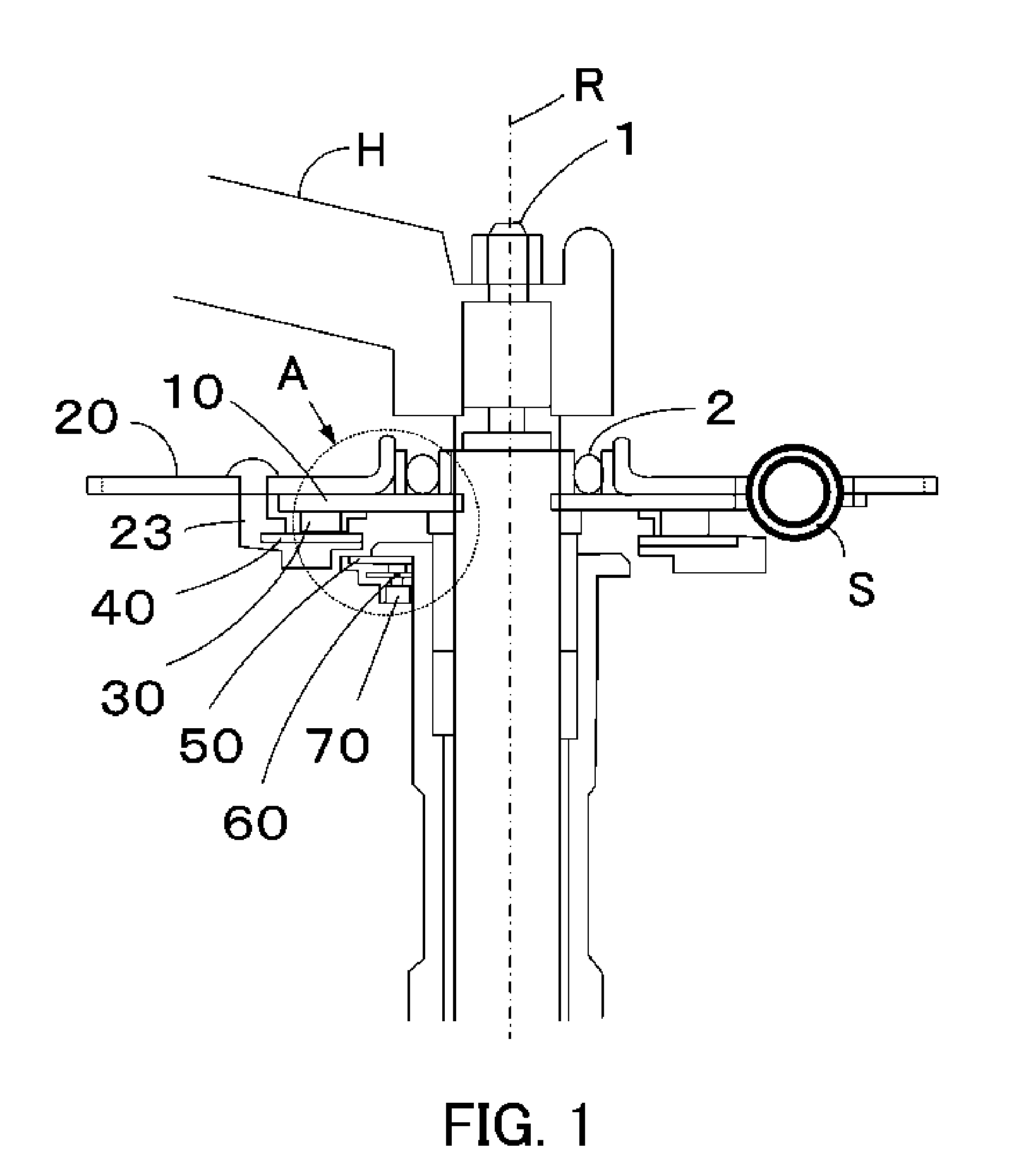
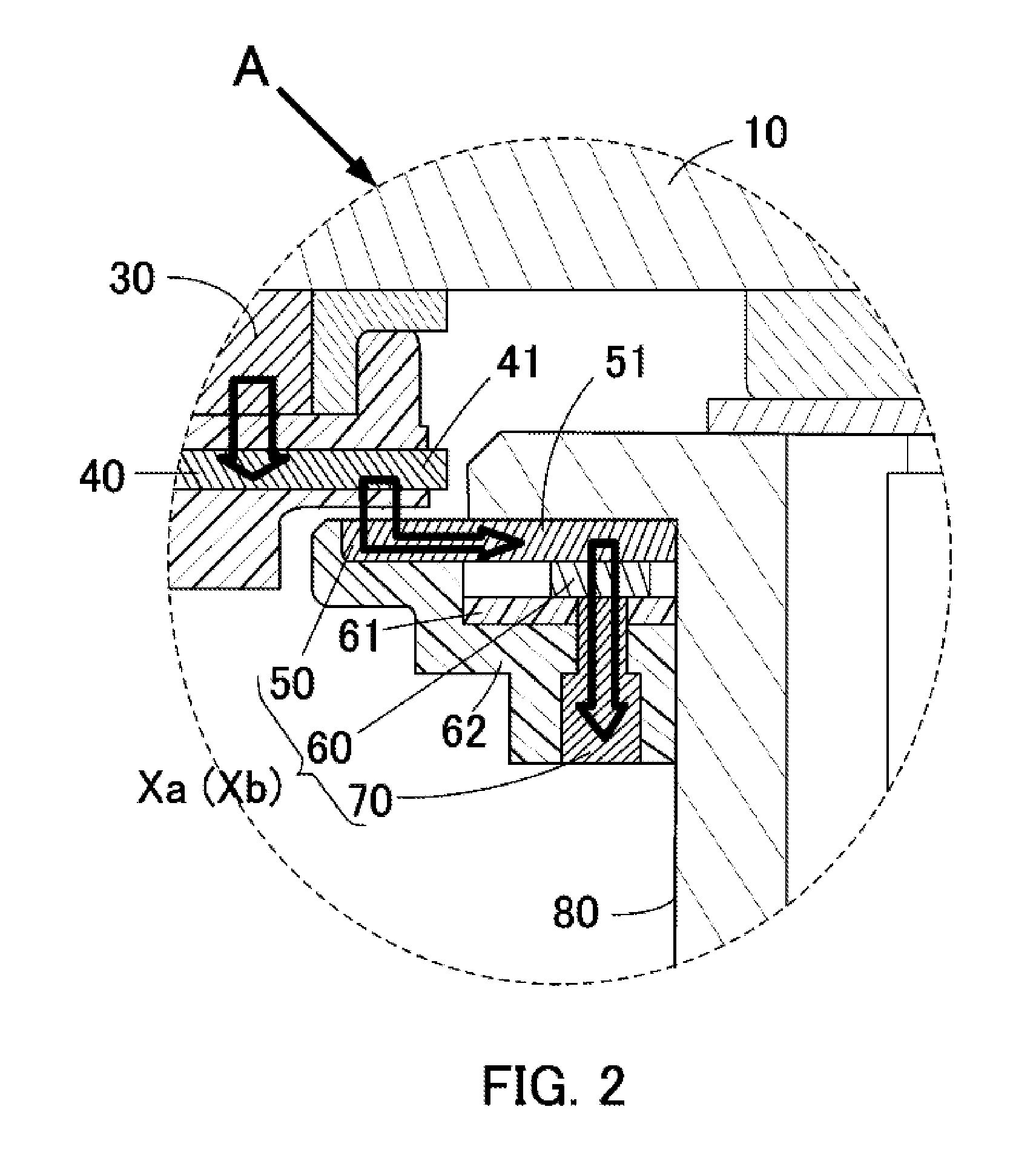
[0063]Hereinafter, an embodiment of the present invention in which a relative rotational angular displacement detection device X according to the present invention is applied to a power assist system for a power assist wheelchair (see FIG. 10) will be explained with reference to the attached drawings. Needless to say, the relative rotational angular displacement detection device according to the present invention is not limited to the case in which the device is used in a power assist system for a power assist wheelchair, and can also be applied to various devices and mechanisms for detecting a relative rotational angular displacement of a pair of rotat...


PUM

PropertyMeasurementUnit
electric angleaaaaaaaaaa

Abstract

A permanent magnet includes magnetic poles that are arranged so as to alternate in polarity in the circumferential direction of the axis of rotation. The magnet is attached to one of a pair of rotatable members. The rotatable members are relatively rotatable about an axis of rotation. A magnetic flux inducing ring, including an annular ring body and a plurality of protrusions protruding from the ring body, is attached to the other rotatable member. A plurality of magnetic sensors is arranged adjacent to the ring body. A first facing portion and a second facing portion, each for inducing a part of a magnetic flux of the ring body, are provided and do not rotate with the permanent magnet and the magnetic flux inducing ring.

Description

CROSS-REFERENCE TO RELATED APPLICATIONS[0001]This application claims priority under 35 U.S.C. §119 to Japanese Patent Application No. 2012-202580, filed on Sep. 14, 2012, the entire disclosure of which is incorporated herein by reference in its entirety.BACKGROUND OF THE INVENTION[0002]1. Field of the Invention[0003]The present invention relates to, inter alia, a relative rotational angular displacement detection device used to detect a relative rotational angular displacement of a pair of rotatable members arranged coaxially with each other.[0004]More specifically, the present invention relates to a relative rotational angular displacement detection device preferably for use in a power assist system for, e.g., a power assist wheelchair, a power assist bicycle, a power steering wheel, etc. The present invention also relates to a torque detection device using the relative rotational angular displacement detection device, and a torque control device using the relative rotational angul...

Claims


Application Information

Patent Timeline
Patent Type & Authority Applications(United States)
IPC IPC(8): H02P6/00G01L3/10B62D5/04G01B7/30
CPCH02P6/00B62D5/0463G01L3/104G01B7/30B62M6/20B62M6/50G01D5/2451G01L3/1435G01D2205/40
Inventor TANAKA, HIROSHINAKAMURA, KAZUTO
Owner YAMAHA MOTOR CO LTD
Why Eureka
Try Eureka