Microswitch having an integrated electromagnetic coil

Inactive Publication Date: 2014-03-20
HT MICROANALYTICAL
View PDF6 Cites 5 Cited by
  • Summary
  • Abstract
  • Description
  • Claims
  • Application Information

AI Technical Summary

Benefits of technology

The present invention is a microswitch that overcomes limitations of previous designs. It has a movable contact that moves in a flat plane and is actuated by a magnetic field generated by one or more coils. The coils and a closed magnetic path help to efficiently channel the magnetic field through the microswitch. The technical effect of this invention is a more reliable and precise switch that can be used in a variety of applications.

Problems solved by technology

Unfortunately, microfabrication techniques are not well suited to the formation of a moving element whose quiescent state is that of physical contact with another element (e.g., a normally closed switch).
As a result, prior-art microsystem-based switching devices have been principally limited to normally open operation.
Implementing an integrated electromagnetic coil within a planar process can be quite challenging, however.
Coils having poor magnetic coupling require a great deal of electrical power to generate sufficient force to energize the switch, however.
This has significantly limited their widespread adoption.
Macro coils that are formed separate from the switch and then integrated with the device significantly increase packaging cost and device size.
In addition, they also typically have poor assembly tolerances that can lead to wide variation in the operating characteristics for a given device design.

Method used


Image

  • Microswitch having an integrated electromagnetic coil
  • Microswitch having an integrated electromagnetic coil
  • Microswitch having an integrated electromagnetic coil

Examples


Embodiment Construction

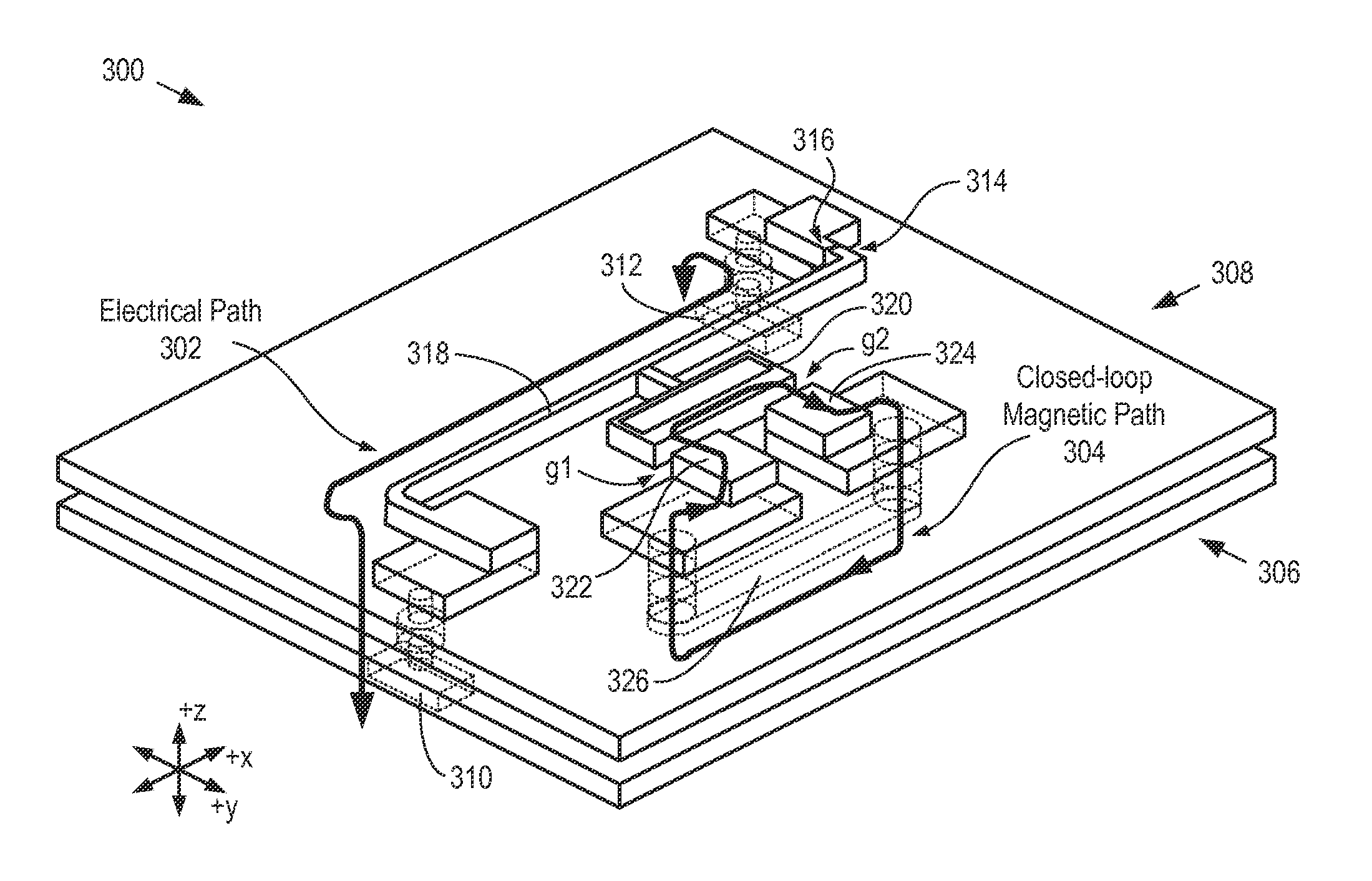
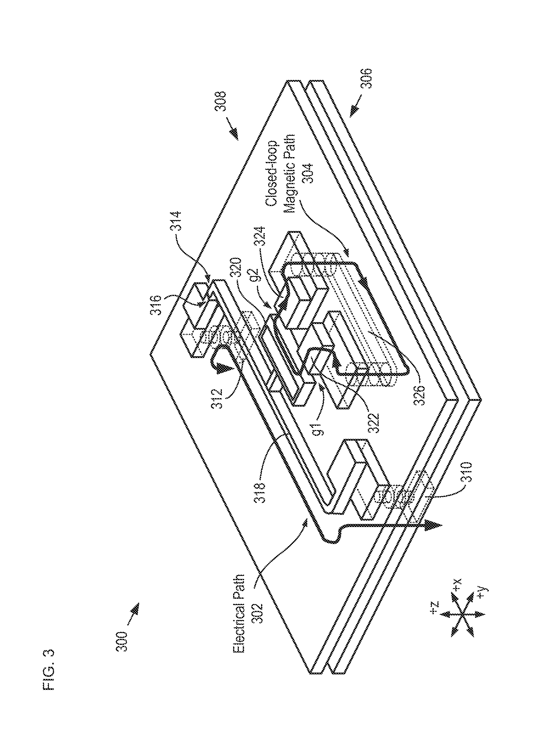
[0039]As discussed in parent case U.S. patent application Ser. No. 13 / 764,424, microfabrication technology lends itself to the formation of switching elements that move in a direction perpendicular to its underlying substrate—referred to as “vertically actuated” elements. In part, this is because a working gap having a relatively large cross-section and small gap distance can be formed in a relatively straight-forward manner for a vertically actuated device. It is also relatively straightforward to form a planar coil that generates a magnetic field directed in the vertical direction. It is difficult, if not impossible, however, to form a vertically actuated device via microfabrication technology, where the device has an efficient magnetic circuit that has a compact magnetic path.

[0040]An additional challenge for vertically actuated switches is that their operating characteristics are determined primarily by the thin-film properties of the layers from which the movable elements are f...


PUM

PropertyMeasurementUnit
Magnetic fieldaaaaaaaaaa
Magnetismaaaaaaaaaa

Abstract

A microswitch is disclosed, wherein the microswitch has (1) an electrical path between a first terminal and a second terminal and (2) a closed-loop magnetic path for channeling a magnetic field through a working gap to efficiently actuate the microswitch, where the electrical path and the closed-loop magnetic path are path independent. The electrical path includes a laterally movable mechanically active element. The closed-loop magnetic path includes one or more integrated coils for generating the magnetic field. The microswitch comprises: an electromagnetic module, which includes the one or more coils and some of the magnetic element of the closed-loop magnetic path; and a switch module, which includes the switching elements and the remainder of the magnetic elements of the closed-loop magnetic path. After the modules are joined the magnetic elements on both modules are magnetically coupled to collectively define the closed-loop magnetic path.

Description

CROSS REFERENCE TO RELATED APPLICATIONS[0001]This case is a continuation-in-part of co-pending U.S. patent application Ser. No. 13 / 764,424, filed Feb. 11, 2013 (Attorney Docket: 515-006US3), which is a continuation-in-part of U.S. patent application Ser. No. 13 / 587,398, filed Aug. 16, 2012 (Attorney Docket: 515-006US2), which is a continuation of U.S. patent application Ser. No. 13 / 028,855 (now U.S. Pat. No. 8,258,900), filed Feb. 16, 2011 (Attorney Docket: 515-006US), which is a continuation of U.S. patent application Ser. No. 11 / 367,890 (now U.S. Pat. No. 7,999,642), filed Mar. 3, 2006 (Attorney Docket: 515-003US), which claims priority to U.S. Provisional Patent Application Ser. No. 60 / 658957, filed Mar. 4, 2005 (Attorney Docket: 31790-05-01P) and U.S. Provisional Patent Application Ser. No. 60 / 658,902, filed Mar. 4, 2005 (Attorney Docket: 31790-05-02P). Each of these cases is incorporated by reference herein.[0002]The underlying concepts, but not necessarily the language, of the...

Claims


Application Information

Patent Timeline
IPC IPC(8): H01H51/00H01H49/00
CPCH01H49/00H01H51/00H01H50/005H01H2001/0078H01H2050/007Y10T29/4902
Inventor CHRISTENSON, TODD RICHARD
Owner HT MICROANALYTICAL
Why Eureka
Try Eureka