Contactless potentiometer

a contactless potentiometer and magnetic technology, applied in the direction of auxillary driving means, adjustable resistors, instruments, etc., to achieve the effect of reducing the siz

Inactive Publication Date: 2014-03-20
NIDEC SERVO CORP
View PDF9 Cites 11 Cited by
  • Summary
  • Abstract
  • Description
  • Claims
  • Application Information

AI Technical Summary

Benefits of technology

[0009]Preferred embodiments of the present invention provide a contactless potentiometer capable of being reduced in size, capable of accommodating not only a rotational angle detection element but also a circuit that processes a detection signal supplied from the detection element, and capable of coping with an additional functional demand without having to significantly change the potentiometer.
[0011]With the contactless potentiometer according to a preferred embodiment of the present invention, the magnet is held in the tip end portion of the shaft supported on the housing and is arranged within the sensor area. The sensor IC is mounted on the circuit board attached to the sensor-area-side surface of the cover member in a facing relationship with the magnet. It is therefore possible to arrange the magnet and the sensor IC along the axial direction of the shaft. Unlike with a conventional potentiometer, there is no likelihood that the overall size of the potentiometer becomes larger in the radial direction of the shaft. The circuit board is mounted to the cover member. The peripheral circuit of the sensor IC mounted on the circuit board can also be mounted on the circuit board. It is therefore possible to output an output signal indicating the rotational angle of the shaft. In particular, the recess portion is arranged on the surface of the cover member facing the circuit board and is arranged to face the circuit board. Therefore, a component can be mounted on the surface of the circuit board facing the recess portion. The circuit configuration relating to the sensor IC can be appropriately changed without having to change the structures of the circuit board, the housing and the cover member. This makes it possible to cope with every change of the specifications.

Problems solved by technology

Since the sensor area can be hermetically sealed, the contactless potentiometer can be used in an outdoor area with a disadvantageous working environment requiring a dust proof and water proof characteristic.

Method used


Image

  • Contactless potentiometer
  • Contactless potentiometer
  • Contactless potentiometer

Examples


first preferred embodiment

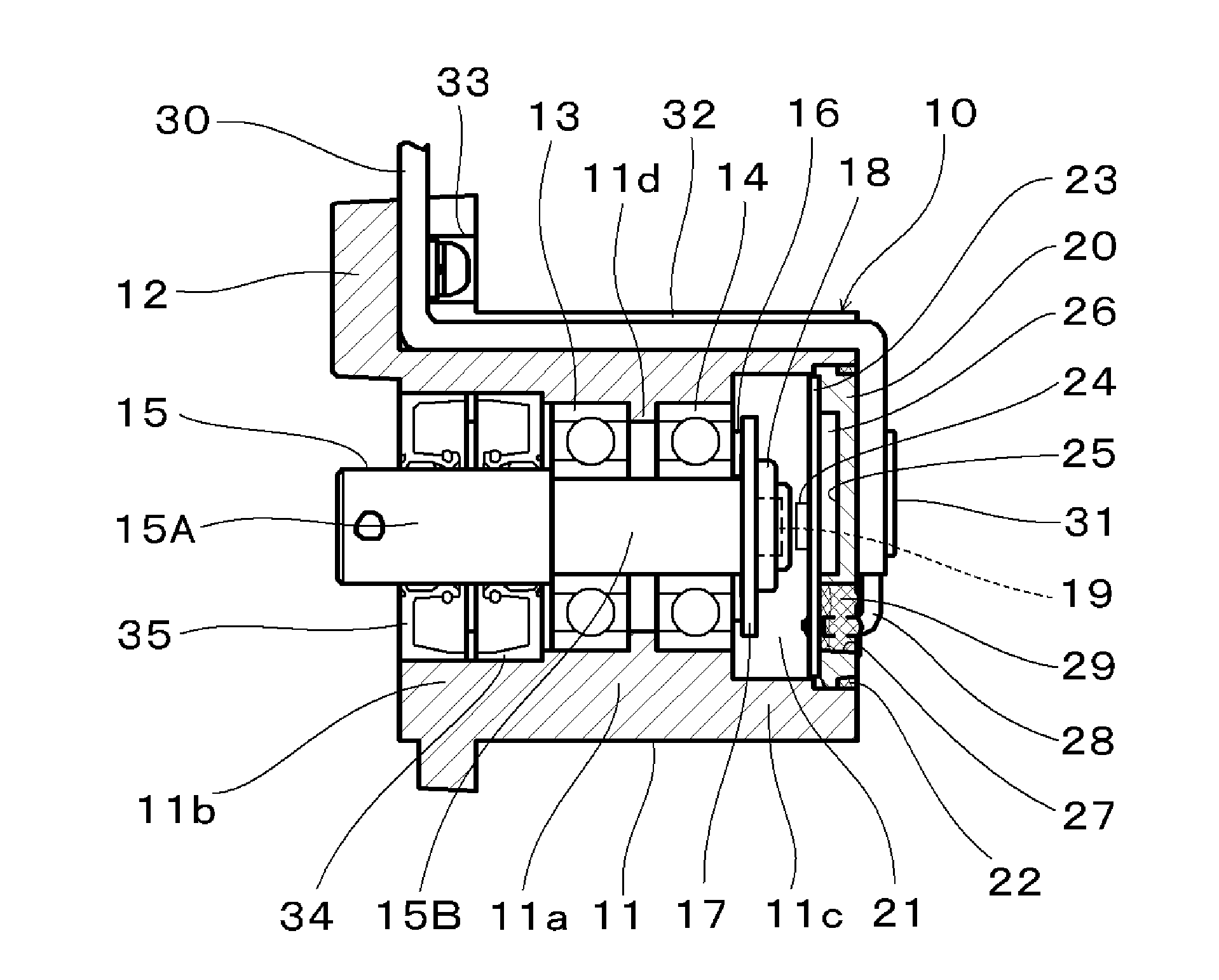
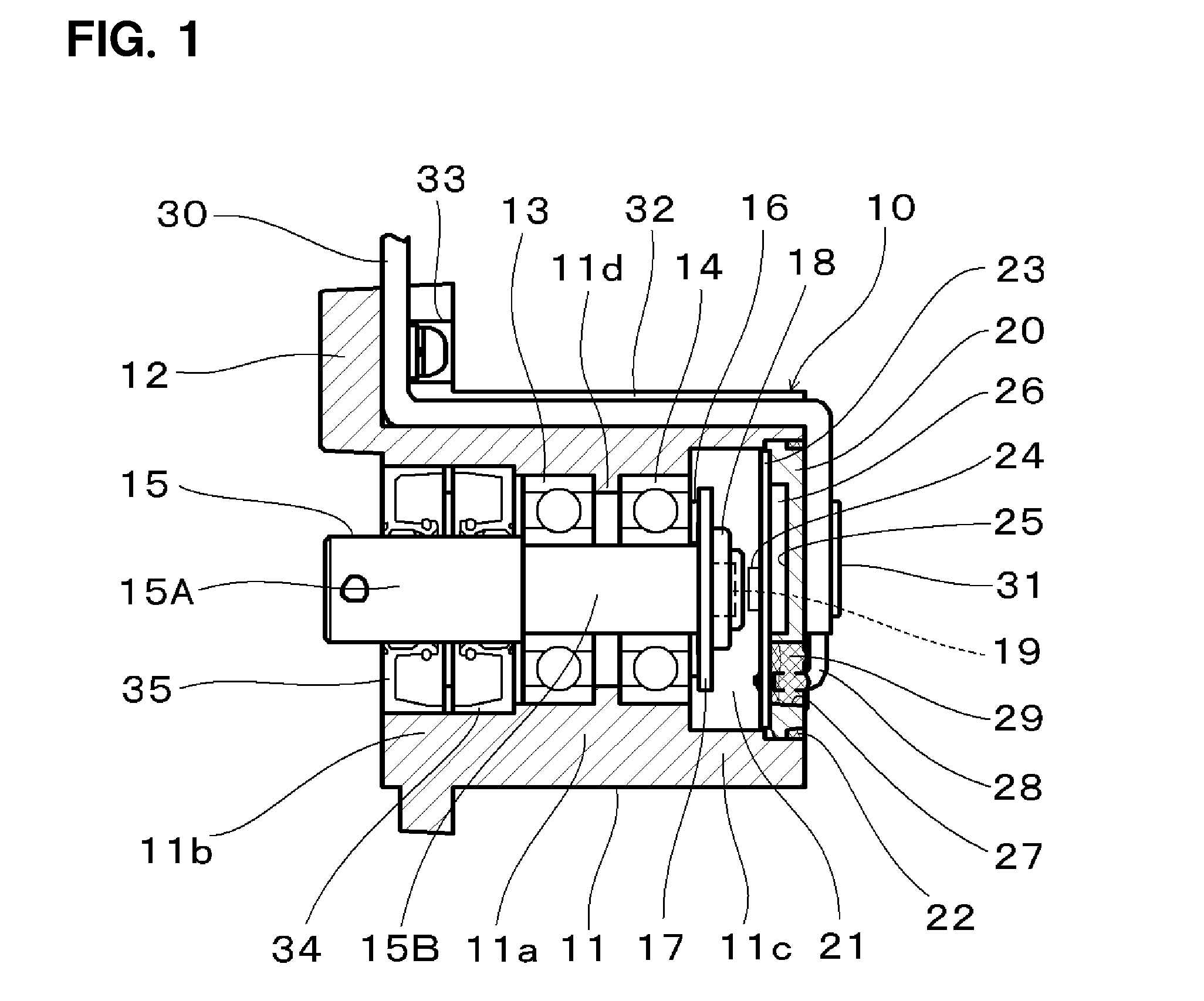
[0021]A contactless potentiometer according to a first preferred embodiment of the present invention will be described with reference to FIGS. 1 through 3. FIG. 1 is a sectional view of the contactless potentiometer taken along an axis of a shaft. FIG. 2 is a front view of the contactless potentiometer. The contactless potentiometer preferably includes a housing 10 as an outer shell. The housing 10 preferably includes a cylindrical body portion 11 and a flange portion 12 integrally defined with a base of the body portion 11. The housing 10 is preferably made of, e.g., a non-magnetic metallic material or a resin material. The body portion 11 preferably includes a middle bearing holder portion 11a, a base-side sealing portion 11b having an inner diameter a little larger than an inner diameter of the bearing holder portion 11a, and a tip-end-side sensor portion 11c having an inner diameter larger than an inner diameter of the sealing portion 11b. A pair of bearings 13 and 14 defined by...

second preferred embodiment

[0033]FIGS. 4 and 5 show a contactless potentiometer according to a second preferred embodiment of the present invention. FIG. 4 is a sectional view of the contactless potentiometer taken along the axis of a shaft. FIG. 5 is a front view of the contactless potentiometer. In FIGS. 4 and 5, the same reference symbols as used in FIGS. 1 and 2 designate identical or substantially equivalent components or elements.

[0034]The housing 10 preferably includes the body portion 11 and the flange portion 12. Unlike the first preferred embodiment, the flange portion 12 is preferably integrally defined with the middle bearing holder portion 11a of the body portion 11 not the base of the body portion 11. The body portion 11 is larger in diameter than the body portion 11 of the first preferred embodiment. The shaft 15 preferably includes the base-side large diameter portion 15A and the tip-end-side middle diameter portion 15B. The smaller diameter portion 15B is supported by the bearings 13 and 14 a...

third preferred embodiment

[0039]FIG. 6 is a sectional view of a contactless potentiometer according to a third preferred embodiment of the present invention, which is taken along the axis of a shaft. The same reference symbols as used above designate identical or equivalent portions.

[0040]The contactless potentiometer of the third preferred embodiment of the present invention is larger in size than the contactless potentiometers of the first and second preferred embodiments of the present invention. The flange portion 12 is preferably defined as a monolithic member with the body portion of the housing 10 at the outer circumference side of the sensor portion 11c. The cover member 20 is wholly arranged at the inner circumference side of the sensor portion 11c. The end surface of the cover member 20 is brought into contact with the side surface of the bearing holder portion 11a. Thus, the sensor area 21 is defined between the bearing holder portion 11a and the cover member 20. In case of the first and second em...


PUM


Abstract

A contactless potentiometer includes a shaft and a magnet rotatable together with the shaft and detects a rotational angle of the shaft corresponding to a change in magnetic fields caused by the rotation of the magnet, the magnet being held in a tip end portion of the shaft. The potentiometer includes a cover member attached to a housing at a tip end side of the shaft and arranged to define a closed sensor area between the cover member and the housing, and a circuit board mounted to the cover member at a side of the sensor area in a perpendicular or substantially perpendicular relationship with the shaft. The cover member includes a recess portion arranged on a surface of the cover member facing the circuit board, the recess portion cooperating with the circuit board to define a component-mounting spare space.

Description

BACKGROUND OF THE INVENTION[0001]1. Field of the Invention[0002]The present invention relates to a magnetic contactless potentiometer arranged within an electric device or an industrial device and used to detect a rotation position.[0003]2. Description of the Related Art[0004]Conventionally, a contactless potentiometer used as an angular sensor is known. As disclosed in, e.g., Japanese Patent Application Publication No. 2006-242915 (JP2006-242915A), there is available a contactless potentiometer in which a disc-shaped magnet fixed to a shaft is formed into a substantially cylindrical columnar shape such that the outer peripheral portion of the magnet has a thickness varying in the circumferential direction. In this contactless potentiometer, the rotational position of the shaft is detected by changing an output voltage of a Hall element depending on the variation of the thickness of the magnet facing the Hall element arranged at one side of the magnet.[0005]As disclosed in, e.g., Ja...

Claims


Application Information

Patent Timeline
Patent Type & Authority Applications(United States)
IPC IPC(8): H01C10/10
CPCH01C10/103G01D5/145
Inventor HORIGUCHI, MASAHIROYAMANOI, MASARU
Owner NIDEC SERVO CORP
Why Eureka
Try Eureka