Check patentability & draft patents in minutes with Patsnap Eureka AI!

Variable polarization separation via beam splitter rotation

a beam splitter and variable polarization technology, applied in the direction of optical radiation measurement, instruments, polarising elements, etc., can solve the problems of increasing cost and complexity, increasing size, and conventional approaches to polarization control

Active Publication Date: 2014-03-20
INTUITIVE SURGICAL OPERATIONS INC
View PDF8 Cites 6 Cited by
  • Summary
  • Abstract
  • Description
  • Claims
  • Application Information

AI Technical Summary

Benefits of technology

This patent describes an apparatus for separating polarization of light using a rotatable beam splitter. The beam splitter can be rotated manually or automatically to change the polarization of input light to output light with a different polarization. The apparatus can be used in an optical network for testing fiber optic equipment, and can be controlled to align with different polarizations. The technical effects of this invention include improved polarization control and improved testing accuracy for optical equipment.

Problems solved by technology

Although a two loop polarization controller can be used to achieve polarization rotation about an axis, or even more sophisticated solutions can be used, these conventional approaches to polarization control suffer several disadvantages.
For example, since standard single mode fiber suffers loss when bent tightly, the two loop paddles must either be large or use low bend loss fiber.
The large size issue is compounded by the fact that paddles also rotate on an edge so that the swept area during rotation is large, thereby necessitating a large enclosure for this kind of polarization control product.
This requires additional axis of motion for automated solutions further adding to size, but also adding to cost and complexity.
Although these devices can be smaller than the conventional paddle-based polarization controllers, they are costly and require special high voltage power supplies.

Method used


Image

  • Variable polarization separation via beam splitter rotation
  • Variable polarization separation via beam splitter rotation
  • Variable polarization separation via beam splitter rotation

Examples


Embodiment Construction

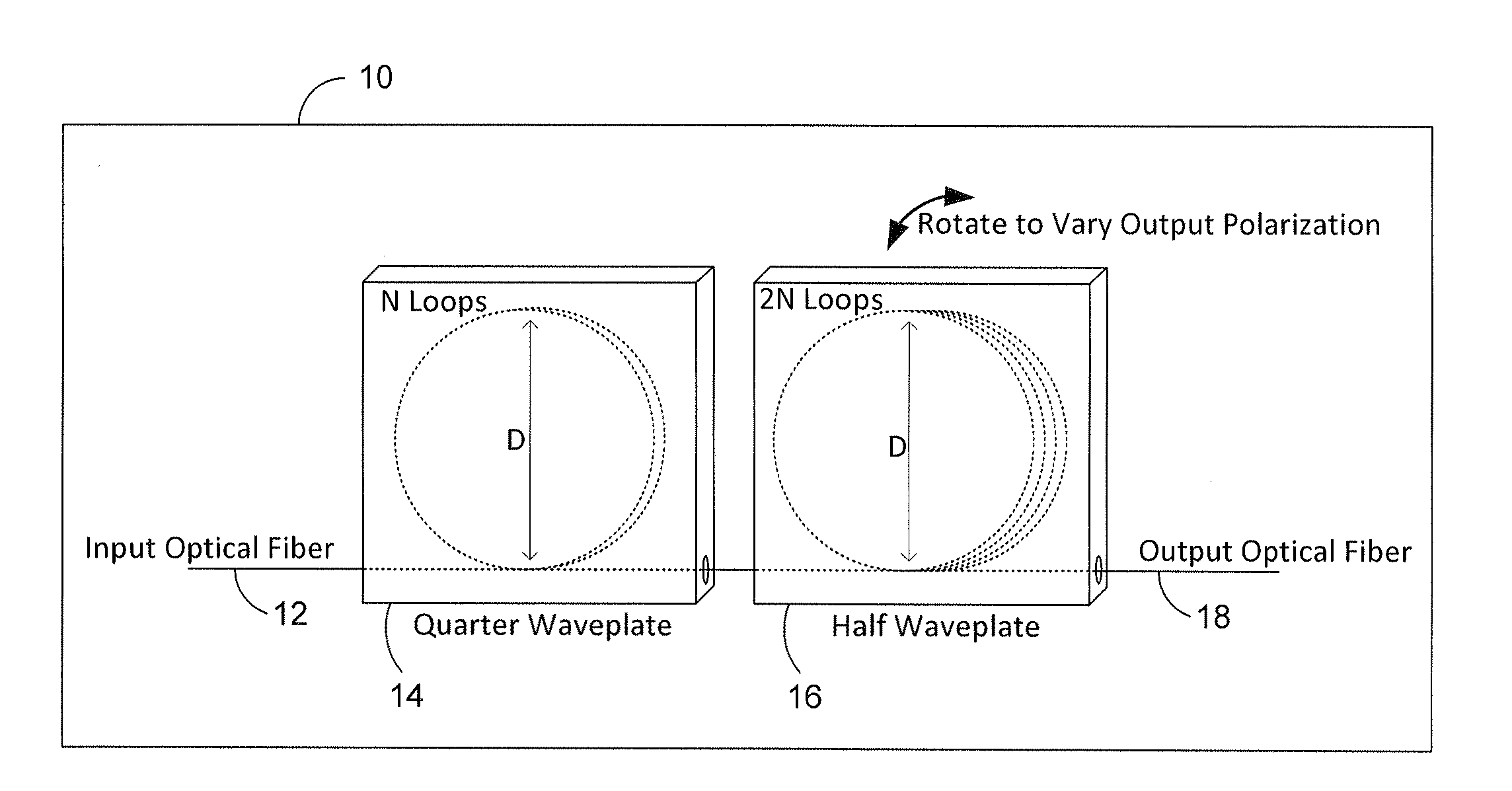
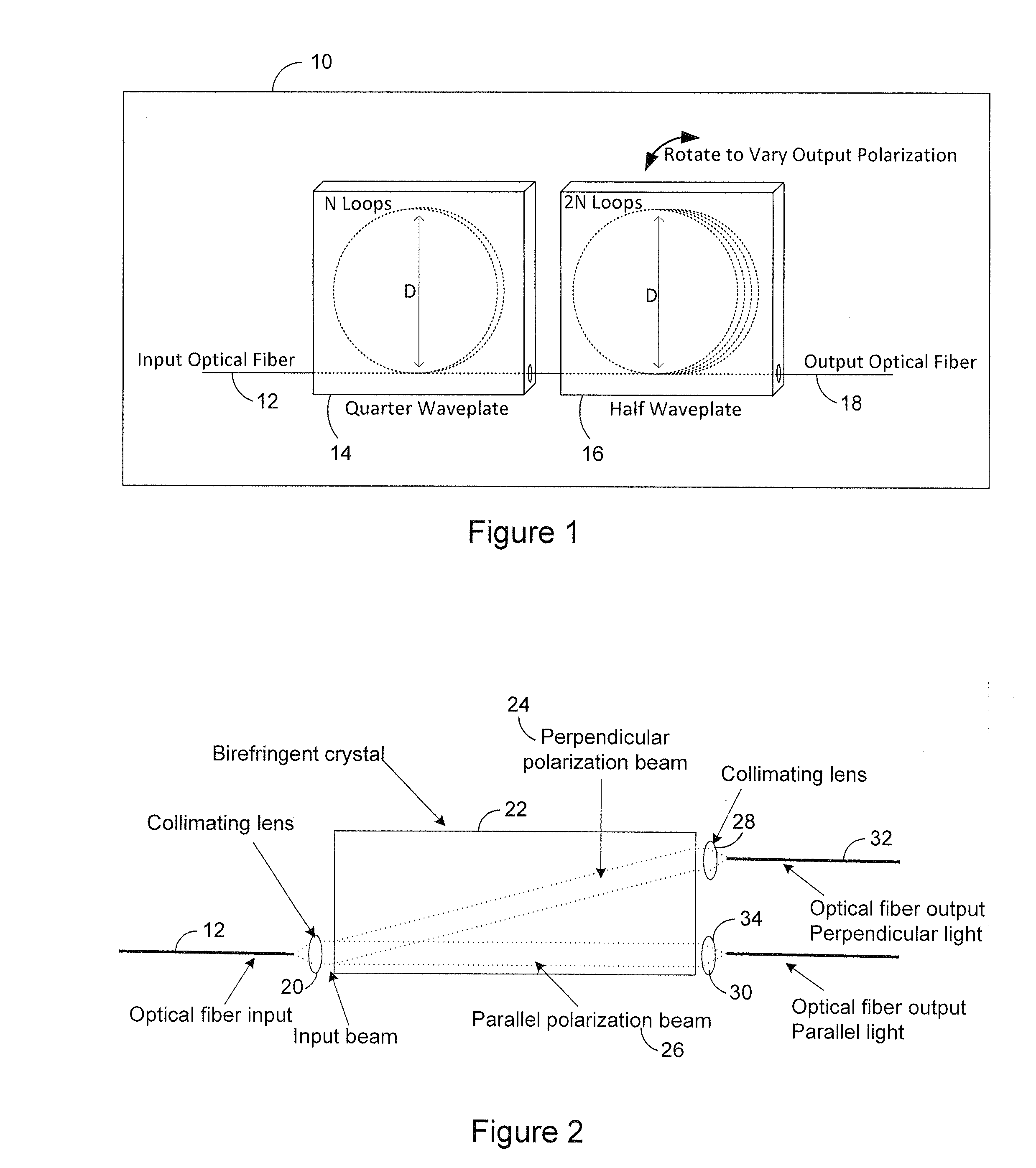
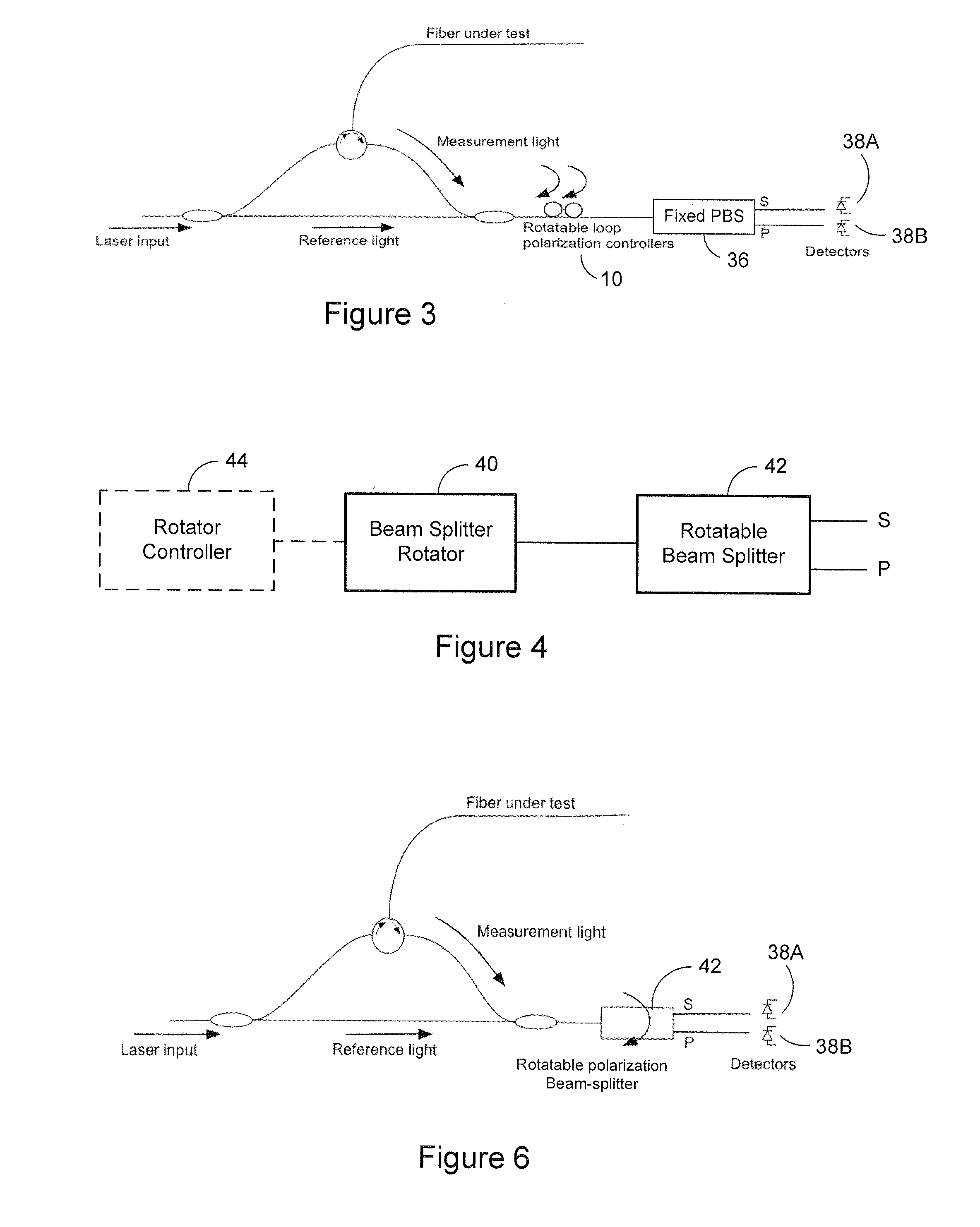
[0035]The following description sets forth specific details, such as particular embodiments for purposes of explanation and not limitation. But it will be appreciated by one skilled in the art that other embodiments may be employed apart from these specific details. In some instances, detailed descriptions of well known methods, interfaces, circuits, and devices are omitted so as not to obscure the description with unnecessary detail. Individual blocks are shown in the figures corresponding to various nodes. Those skilled in the art will appreciate that the functions of those blocks may be implemented using individual hardware circuits, using software programs and data in conjunction with a suitably programmed digital microprocessor or general purpose computer, and / or using applications specific integrated circuitry (ASIC), and / or using one or more digital signal processors (DSPs). Software program instructions and data may be stored on a non-transitory, computer-readable storage me...


PUM


Abstract

An apparatus for separating polarization of light includes a rotatable beam splitter including an input for receiving light with a first polarization and an output for outputting light with a second polarization different from the first polarization. Rotation of the rotatable beam splitter changes the first polarization of the input light to the second polarization of the output light. An optical network and method are also set forth.

Description

PRIORITY APPLICATION[0001]This application claims priority from U.S. provisional patent application serial number 61 / 489,124, filed on May 23, 2011, the contents of which are incorporated herein by reference.TECHNICAL FIELD[0002]The technology relates to polarization control and may be used for example in optical fiber applications.INTRODUCTION[0003]Controlling the polarization state of light in an optical fiber is often required in optical fiber networks. Polarization control allows tasks such as alignment of fiber optic networks, balancing of power between a set of optical detectors, and probing a device under test with different launch polarization states to be performed. The polarization response of an optical network can be monitored using an industry technique known as polarization diverse detection where the polarization response of the light is split into one or more states and detected at respective optical detectors. Adding a polarization controller into this scheme permit...

Claims


Application Information

Patent Timeline
IPC IPC(8): G02B27/28G01J4/00
CPCG01J4/00G02B27/283G02B6/2706
Inventor SANBORN, ERIC E.FROGGATT, MARK E.
Owner INTUITIVE SURGICAL OPERATIONS INC
Features
  • R&D
  • Intellectual Property
  • Life Sciences
  • Materials
  • Tech Scout
  • Unparalleled Data Quality
  • Higher Quality Content
  • 60% Fewer Hallucinations
Learn More