Airport surface collision-avoidance system (ASCAS)

a collision avoidance and airport technology, applied in the field of airport surface collision avoidance systems, can solve the problems of pilots misjudging the clearance distance available, unable to reliably provide the pilot with clearance information, and the lack of depth perception inherent in a two-dimensional camera display

Active Publication Date: 2014-03-20
HONEYWELL INT INC
View PDF2 Cites 12 Cited by
  • Summary
  • Abstract
  • Description
  • Claims
  • Application Information

AI Technical Summary

Benefits of technology

[0004]The present invention provides systems and methods for performing airport surface collision-avoidance. A wingtip-mounted camera allows the pilot to positively ascertain that the wingtip will clear objects located in the video. An exemplary system implemented on an aircraft includes a

Problems solved by technology

Extensive monetary damage and potential human injury are experienced each year due to the collision of large aircraft wingtips with ground facilities and other aircraft.
The principal reason for these collisions appears to be the pilot misjudging the clearan

Method used


Image

  • Airport surface collision-avoidance system (ASCAS)
  • Airport surface collision-avoidance system (ASCAS)
  • Airport surface collision-avoidance system (ASCAS)

Examples


Embodiment Construction

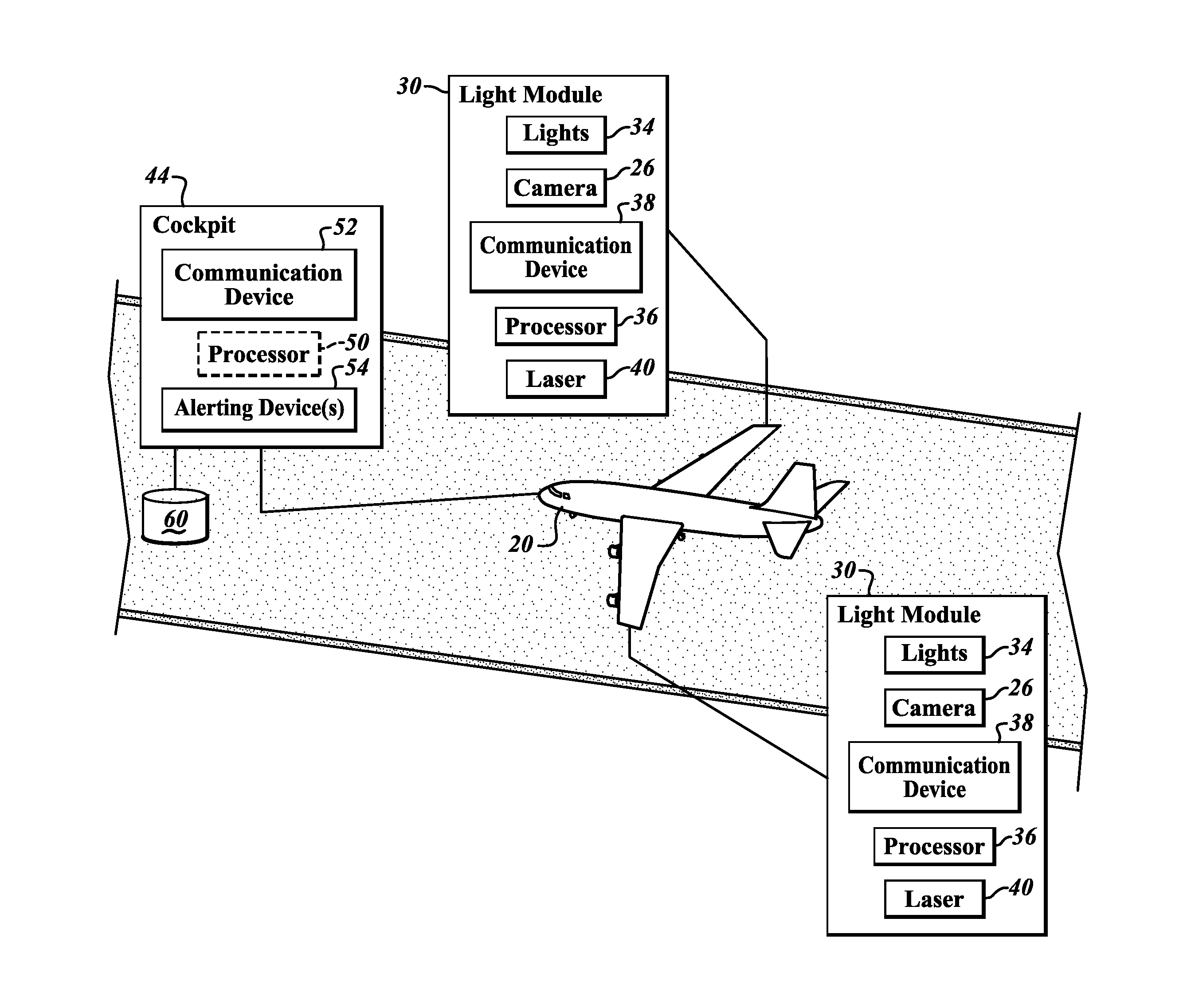
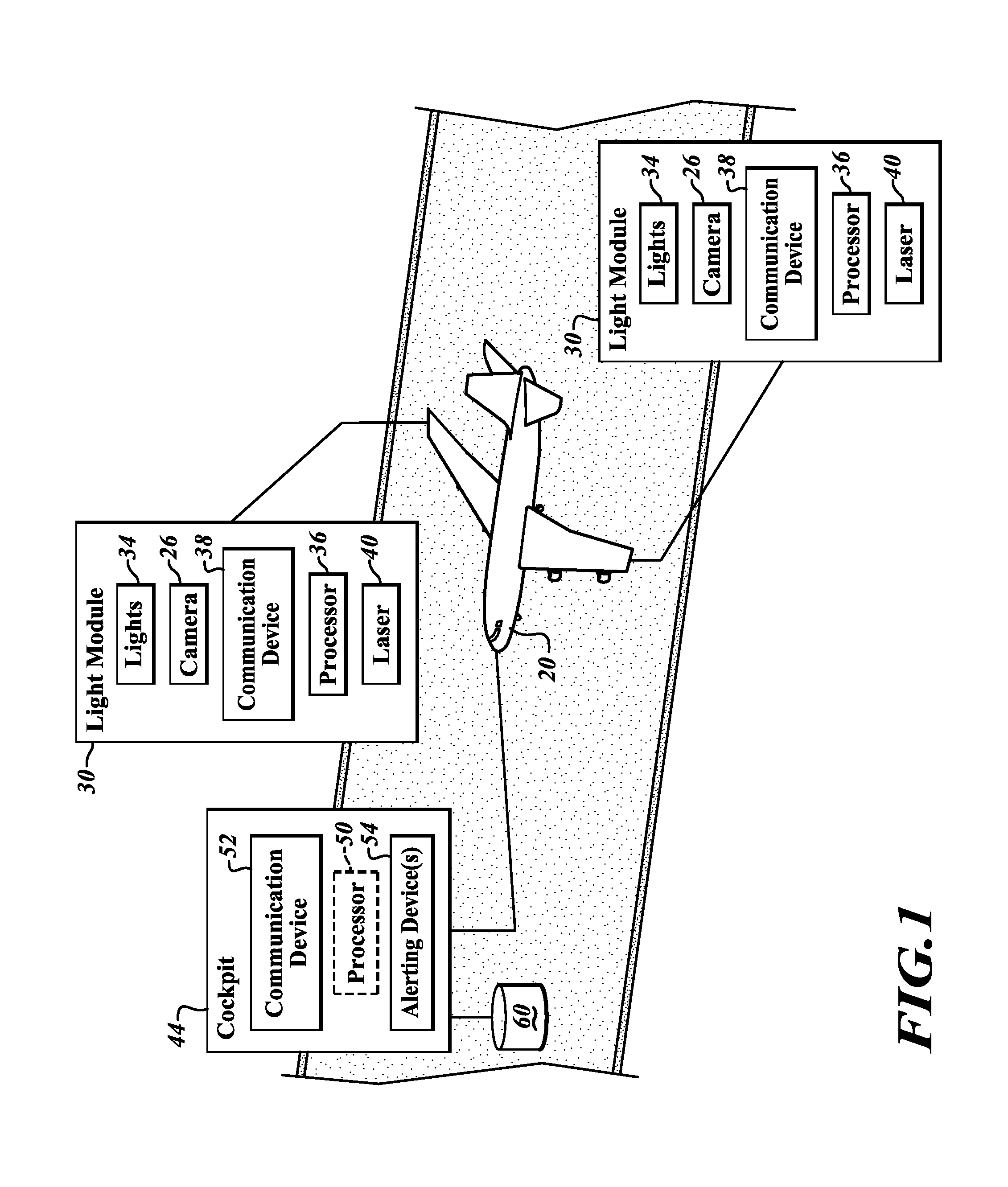
[0014]In one embodiment, as shown in FIG. 1, an aircraft 20 includes cameras 26 that are incorporated within wingtip-mounted aircraft light modules 30 or located at other parts of the aircraft 20. The light modules 30 also include navigation / position lights 34, a processor 36 (optional), a communication device 38, and a laser (optional) 40. The cameras 26 are in communication (wired or wirelessly) with a user interface (UI) device 44 via the communication device 38.

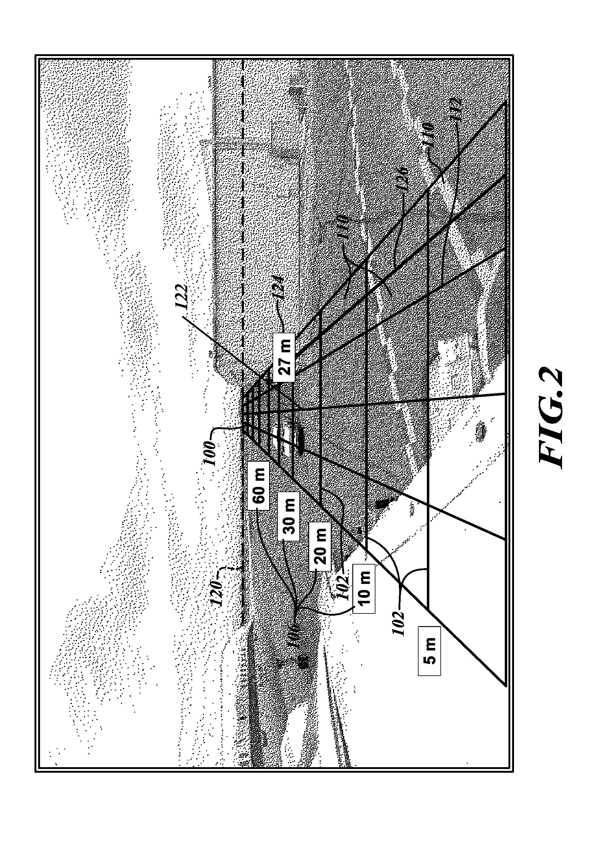
[0015]The UI device 44 includes a processor 50 (optional), a communication device (wired or wireless) 52, and a display device 54. The UI device 44 provides visual presentations that include the video generated by the cameras with reference information (e.g., a reticule).

[0016]In one embodiment, the camera 26 includes a microcamera located at the wingtip within the light module 30 that includes the lights 34 (e.g., LED lights), which occupy less space than traditional aircraft navigation lights. The camera 26 is aimed alo...


PUM


Abstract

Systems and methods for performing airport surface collision-avoidance. A wingtip-mounted camera allows the pilot to positively ascertain that the wingtip will clear objects located in the video. An exemplary system implemented on an aircraft includes a wingtip module having a camera that generates a video stream and a communication device that transmits the generated video stream. A processor receives the video stream and generates a reticule for the video stream. A display device simultaneously presents the video stream and the reticule. The reticule includes a horizon line and is based on a focal length of a lens of the camera and height of the camera above ground. The reticule includes curved and/or straight distance lines and curved or straight travel lines. The travel line(s) correspond to at least one aircraft component or a zone of importance and are based on location of the camera and trajectory of the aircraft.

Description

PRIORITY CLAIM[0001]This application claims the benefit of U.S. Provisional Applications Ser. Nos. 61 / 653,297, filed May 30, 2012; and 61 / 706,632, filed Sep. 27, 2012, the contents of which are hereby incorporated by reference.BACKGROUND OF THE INVENTION[0002]Extensive monetary damage and potential human injury are experienced each year due to the collision of large aircraft wingtips with ground facilities and other aircraft. The principal reason for these collisions appears to be the pilot misjudging the clearance distance available for the passage of the wingtip when operating in tight quarters or in unfamiliar facilities.[0003]Cameras have been used on aircraft in various locations, including wingtips, for this sort of application before. However, the lack of depth perception inherent in a two-dimensional camera display cannot reliably provide the pilot with clearance information.SUMMARY OF THE INVENTION[0004]The present invention provides systems and methods for performing airpo...

Claims


Application Information

Patent Timeline
IPC IPC(8): G08G5/04G08G5/06G01S13/93
CPCG08G5/06G08G5/04G08G5/0021G08G5/065B64D47/08G01S13/93
Inventor KIRK, JAMES CHRISTOPHERDUSIK, MATEJDUVAL, JOSEPHVASEK, JIRILAMKIN, ANDREW FANNON
Owner HONEYWELL INT INC
Why Eureka
Try Eureka