
Method and apparatus for distributed generation of multiple configurable ratioed clock domains within a high speed domain

a distributed generation and clock domain technology, applied in the field of computing systems, can solve the problems of increasing processing power of the processor, complicated design, and high frequency path of the chip

Active Publication Date: 2014-03-20
ORACLE INT CORP
View PDF4 Cites 24 Cited by
  • Summary
  • Abstract
  • Description
  • Claims
  • Application Information

AI Technical Summary

Benefits of technology

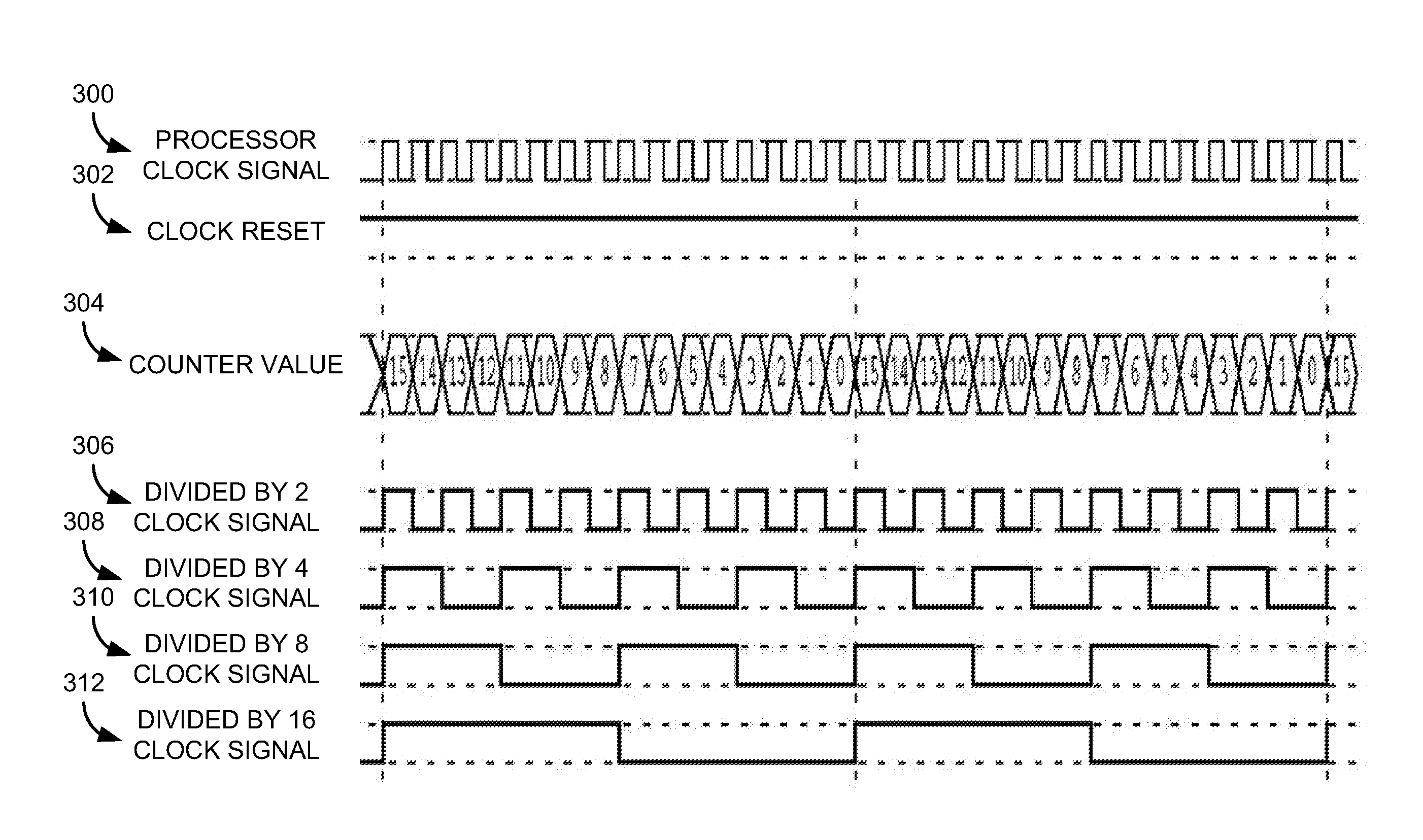
The present disclosure relates to a microprocessor with improved synchronization circuits that generate multiple clock signals. These clock signals are synchronized and ratioed to a processor clock signal, which helps to enable communication between different parts of the microprocessor. The synchronization circuits include counters that generate output value signals that change on each cycle of the processor clock signal. These output value signals are then used to generate a plurality of clock signals that are synchronized with the processor clock signal. These capabilities improve the speed and reliability of the microprocessor, making it more efficient and effective in processing tasks.

Problems solved by technology

In addition, as computers become more commonplace and software becomes more complex, there is a need for the computing devices to perform at faster and faster speeds in smaller and smaller packages.
For example, newer microprocessors often have higher operating frequencies than previous generations of microprocessors, which often results in an increase in processing power for the processor.
However, such high frequency paths in the chip are often costly, both in terms of utilized chip area, hardware costs and power consumed, as well as being more complicated to design.

Method used


Image

  • Method and apparatus for distributed generation of multiple configurable ratioed clock domains within a high speed domain
  • Method and apparatus for distributed generation of multiple configurable ratioed clock domains within a high speed domain
  • Method and apparatus for distributed generation of multiple configurable ratioed clock domains within a high speed domain

Examples


Embodiment Construction

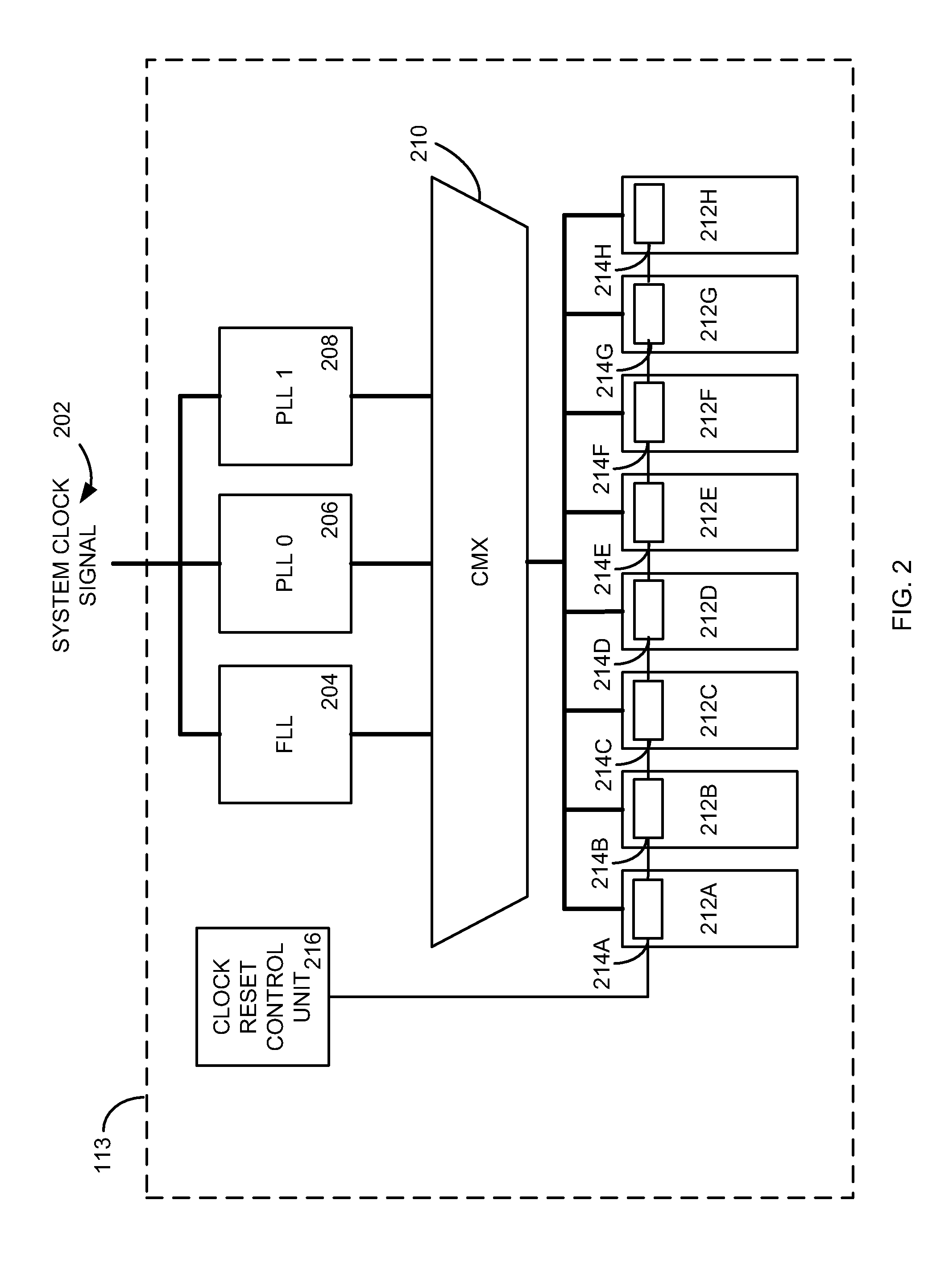
[0019]Implementations of the present disclosure involve an apparatus and / or method for providing one or more distributed clock signals within a processing device. In particular, the present disclosure provides for one or more counter devices integrated into a microprocessor design that operate on a processor clock signal to provide ratioed synchronous clock signals for use by the microprocessor. The counter devices may be associated in a distributed configuration throughout the microprocessor design with one or more domain headers. In this manner, the microprocessor may include a high frequency path for just a processor clock signal to the domain headers and generate other high frequency clock signals at the domains of the processor, saving critical chip space and resources for other aspects of the design as the number and length of high frequency signal paths in the design are reduced.

[0020]Additionally, one or more synchronization pulse signals are also generated from the one or m...


PUM


Abstract

Implementations of the present disclosure involve an apparatus and / or method for providing one or more clock signals within a processing device. In particular, one or more counter devices may be integrated into a microprocessor design that operates on a system clock signal to provide ratioed synchronous clock signals for use by the microprocessor. Additionally, one or more synchronization pulse signals are also generated from the one or more counter devices to facilitate communication between domains of the microprocessor that may operate on separate clock frequencies. Such synchronization pulse signals may also provide for a virtual clock signal within a clock domain to create a low frequency logic cluster within a high frequency domain of the microprocessor. A synchronous, low frequency reset signal is also disclosed to synchronize the counting devices to the system clock without the need for an additional high frequency signal path in the microprocessor design.

Description

FIELD OF THE DISCLOSURE[0001]Aspects of the present invention relate to computing systems and, more particularly, aspects of the present invention involve an apparatus and method for implementing one or more distributed high frequency clock signals in a computing environment, such as a microprocessor device, without the said distributed implementation requiring any shared high speed signals other than a shared clock.BACKGROUND[0002]Computers are ubiquitous in today's society. They come in all different varieties and can be found in places such as automobiles, laptops or home personal computers, banks, personal digital assistants, cell phones, as well as many businesses. In addition, as computers become more commonplace and software becomes more complex, there is a need for the computing devices to perform at faster and faster speeds in smaller and smaller packages. For example, newer microprocessors often have higher operating frequencies than previous generations of microprocessors...

Claims


Application Information

Patent Timeline
Patent Type & Authority Applications(United States)
IPC IPC(8): G06F1/12G06F1/06
CPCG06F1/06G06F1/12G06F1/10
Inventor VAHIDSAFA, ALIMASLEID, ROBERT PAUL
Owner ORACLE INT CORP
Learn More