Flux injection assembly and method

a technology of refining agent and assembly method, which is applied in the direction of heat treatment apparatus, charge manipulation, furnaces, etc., can solve the problems of harmful effluent bi-products, hydrogen evolution, and detrimental to the mechanical properties of solid alloys

Active Publication Date: 2014-03-27
PYROTECK INC
View PDF8 Cites 72 Cited by
  • Summary
  • Abstract
  • Description
  • Claims
  • Application Information

AI Technical Summary

Benefits of technology

[0009]According to a further embodiment of the present disclosure, a flux injector apparatus for distributing flux to a pool of molten metal is provided. The assembly includes a feed mechanism within a pressurized tank. The tank is adapted to store and introduce flux to an inlet of the feed mechanism. The feed mechanism includes a feed wheel within a cavity of a housing having an inlet and an outlet. The feed wheel includes a plurality of notches in selective rotational alignment with the inlet and the outlet for receiving a predetermined amount of flux through the inlet and discharging the flux through the outlet. The inlet of the feed mechanism has an undercut portion at a leading edge to prevent blockage. The outlet of the feed mechanism is aligned with an outlet of the pressurized tank and adapted to be introduced to an associated pool of molten metal.
[0010]One advantage of the present disclosure is an assembly and method of use for a flux injector apparatus to provide a precise amount of flux to a pool of molten aluminum. Another advantage of the present disclosure is an assembly and method that safely stores and measures flux to prevent an overflow of flux provided to the pool of molten aluminum. The assembly also prevents flux overflow and environmental contamination. Yet another advantage of the present disclosure is a mechanism to maintain pressurized gas flow to the hollow shaft while isolating the pressurized tank.

Problems solved by technology

Hydrogen evolves as porosity during the solidification of aluminum alloys and is detrimental to the mechanical properties of the solid alloy.
However, these materials are highly noxious and can cause harmful effluent bi-products.
Improper use of these gasses creates environmental problems.
The proper storage, transport and use of these gasses is burdensome and expensive due to its harmful effects and the associated federal regulations.

Method used


Image

  • Flux injection assembly and method
  • Flux injection assembly and method
  • Flux injection assembly and method

Examples


Embodiment Construction

[0019]It is to be understood that the detailed figures are for purposes of illustrating the exemplary embodiments only and are not intended to be limiting. Additionally, it will be appreciated that the drawings are not to scale and that portions of certain elements may be exaggerated for the purpose of clarity and ease of illustration.

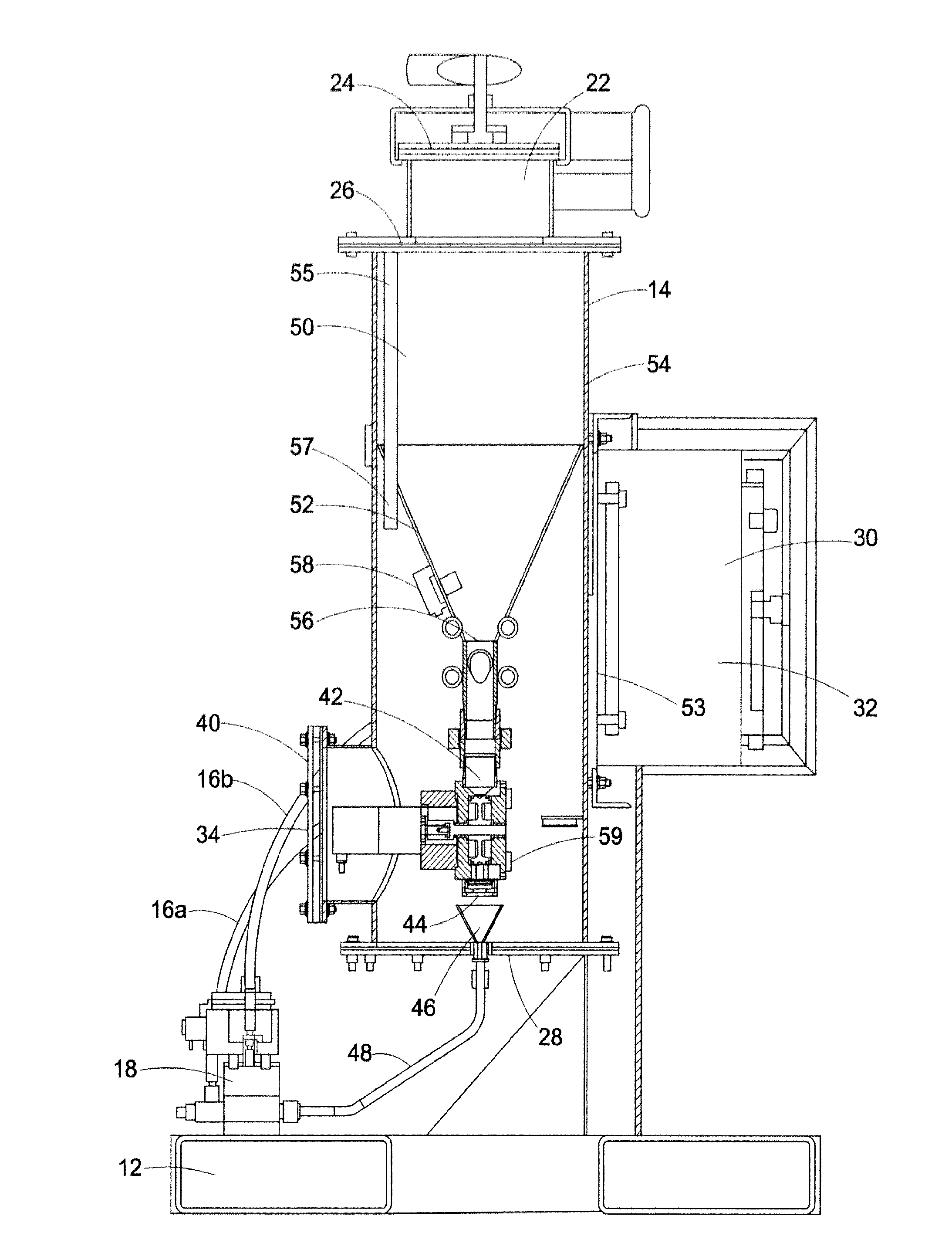
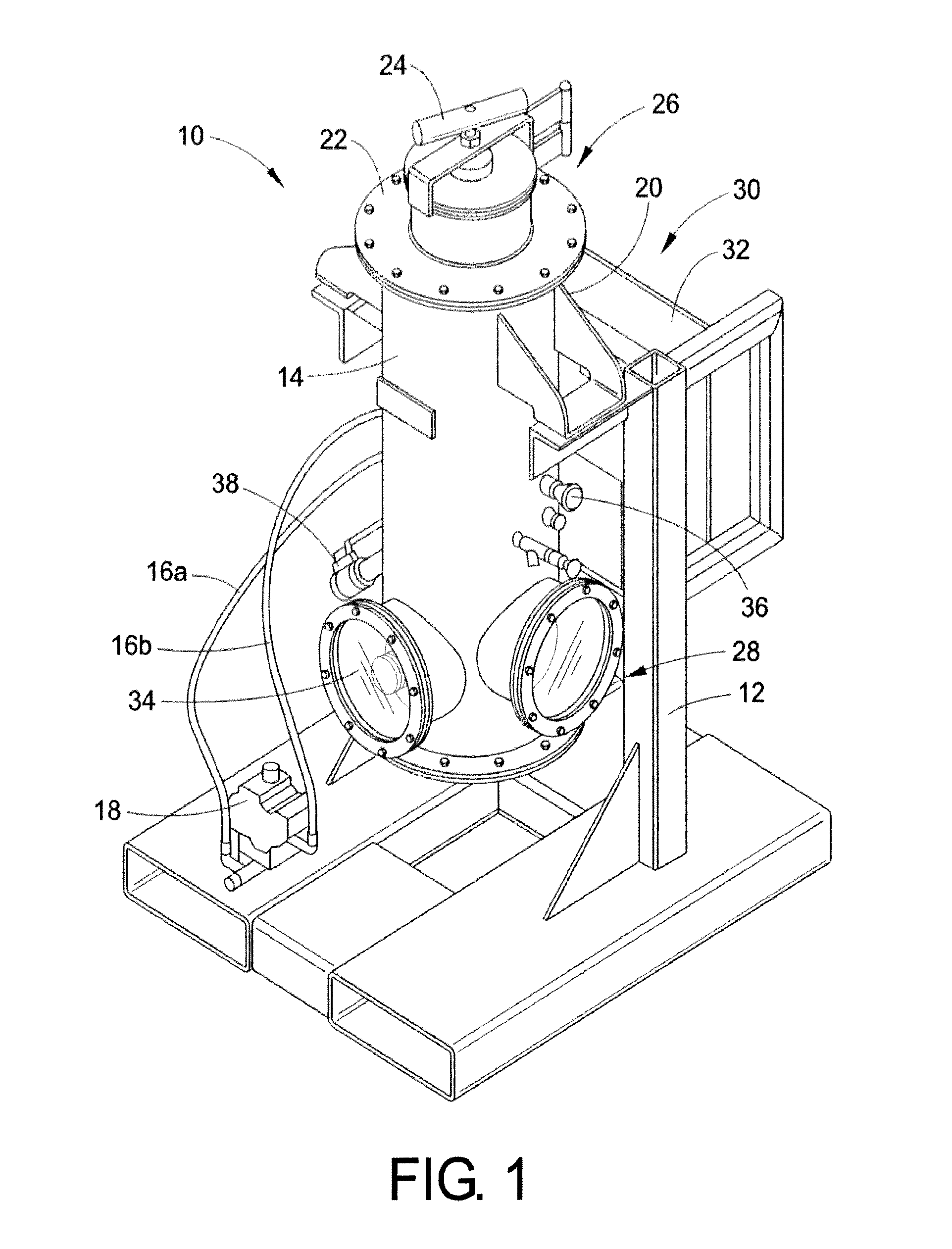
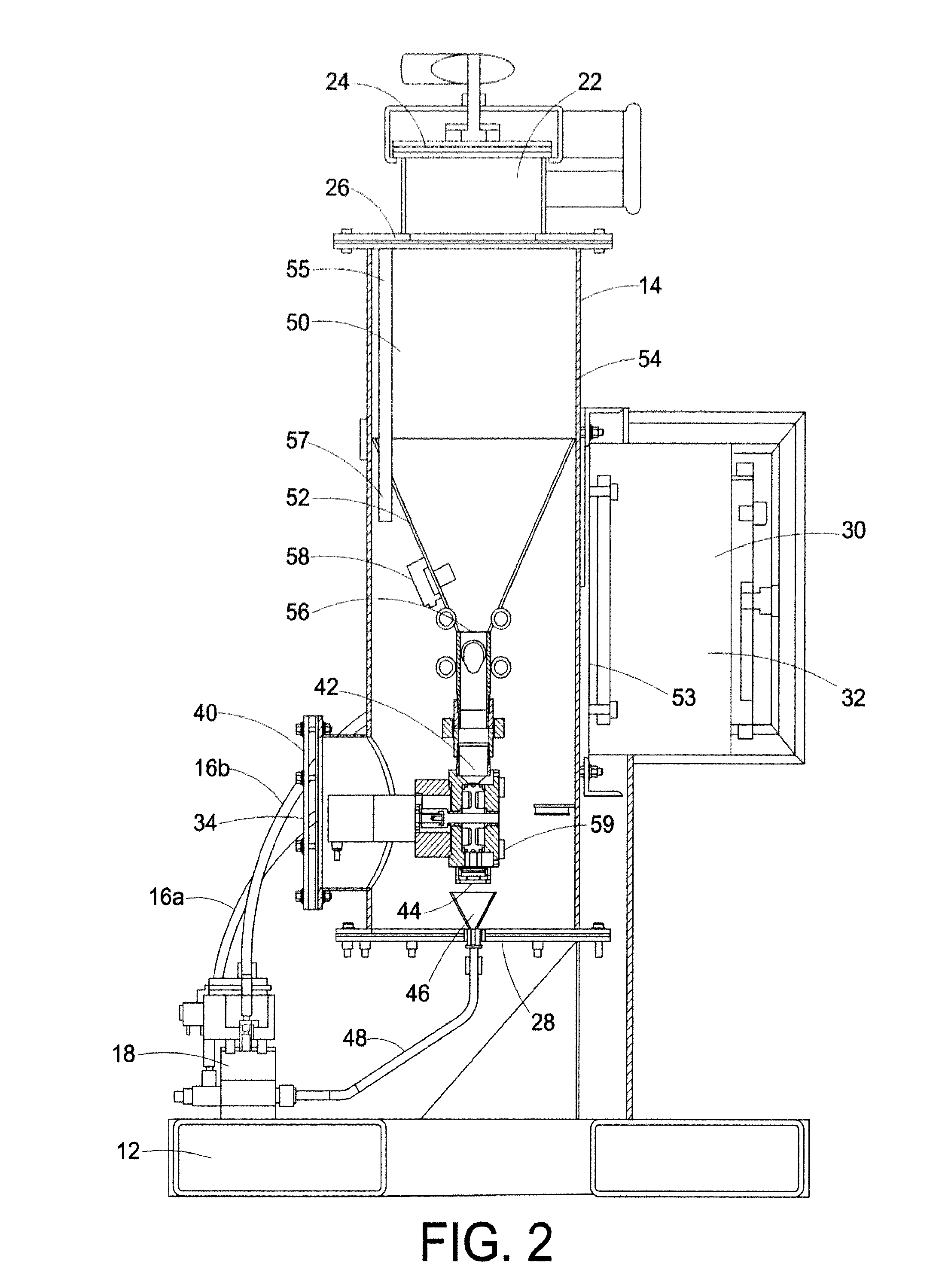
[0020]With reference to FIG. 1, a flux injector assembly 10 is supported by a structural base 12 that maintains the flux injector assembly 10 in an upright position. As used herein, the term “flux” is used to refer to a granulated particulate. An exemplary grain size ranges between about 1 mm to about 3 mm. The flux injector assembly 10 includes a pressurized tank 14 in communication with an isolation mechanism 18. In one embodiment, the isolation mechanism 18 is secured to the structural base 12 and configured to isolate the tank 14 from a flow of independent direct inert gas flow to a hollow shaft of a rotary apparatus (not shown). Moreover, mechanis...


PUM

PropertyMeasurementUnit
grain sizeaaaaaaaaaa
threshold pressureaaaaaaaaaa
pressureaaaaaaaaaa

Abstract

A flux injector apparatus and method adapted to distribute a predetermined amount of flux to an associated pool of molten aluminum. The flux injector apparatus includes a pressurized tank adapted to store and feed the flux under pressure. A feed mechanism operative to discharge a predetermined amount of flux to an outlet and a controller for monitoring and operating the apparatus. The feed mechanism includes a housing having an inner wall defining a cavity with an inlet and an outlet. A feed wheel is positioned within the cavity and operative to receive a predetermined amount of flux from the inlet, translate the flux within the cavity and discharge the predetermined amount of flux through the outlet of the pressurized tank.

Description

BACKGROUND[0001]The present exemplary embodiment relates to an apparatus and method for introducing a refining agent into molten metal. It finds particular application in conjunction with a system for introducing a predetermined amount of chloride flux into a trough of molten aluminum, and will be described with particular reference thereto. However, it is to be appreciated that the present exemplary embodiment is also amenable to other like applications.[0002]Molten metals such as aluminum are known to include high levels of oxide and / or nitride debris that have a negative effect on the solidification of the particular alloy. The melted or liquefied form of aluminum also attracts the formation and absorption of hydrogen within the molten aluminum. Hydrogen evolves as porosity during the solidification of aluminum alloys and is detrimental to the mechanical properties of the solid alloy. Degassing is an effective way of reducing hydrogen caused porosity.[0003]One example of degassin...

Claims


Application Information

Patent Timeline
Patent Type & Authority Applications(United States)
IPC IPC(8): C22B21/06
CPCC22B21/062C22B9/103C22B9/05F27D3/0026C22B21/068F27D3/0025C22B9/10
Inventor LUTES, LENNARDHENDERSON, RICHARD S.HOLSTEIN, JASON
Owner PYROTECK INC
Why Eureka
Try Eureka