Block made of a building material

a building material and block technology, applied in the direction of electrical/magnetic measuring arrangements, antennas, electromagnets, etc., can solve the problems of not being able to allow the remote powering antennas of sensing devices, the inconvenience of using these buried devices, and the poor system performan

Active Publication Date: 2014-03-27
STMICROELECTRONICS INT NV
View PDF1 Cites 58 Cited by
  • Summary
  • Abstract
  • Description
  • Claims
  • Application Information

AI Technical Summary

Benefits of technology

[0015]It may be desirable to be able to supply sensing devices, galvanically isolated and powerable in a contactless fashion, for example, of the type disclosed in the US Patent application No. US 2009 / 0033467 or the Italian Patent application No. ITMI20102365 or PCT application WO 2012 / 084295 in the name of the same applicant, buried in relatively large building structures, without having to bury in the cover portion contactless devices or electric supply lines or antennas of these sensing devices.
[0017]With an external excitation coil or also with a tool of the type used in magnetometers shaped as a horseshoe on which an excitation coil is wound, it is possible to induce from the outside of the block a variable magnetic field in the internal magnetic circuit. This variable magnetic field, conveyed along the whole magnetic circuit or at least along a portion thereof, allows buried sensors to be supplied at relatively great distances from the excitation coil.

Problems solved by technology

Damages are defined as modifications of the material and / or of the geometrical properties of a structural system, comprising modifications of boundary conditions and connections of the system, that worsen performance of the system.
Without them, it may not be possible to allow the remote powering antennas of the sensing devices buried in blocks of building material to receive an electromagnetic field of sufficient intensity for operating the sensing devices.
An inconvenience tied to the use of these buried devices is the limited reliability of the electric connections used for supplying them.
In particular, in the building structures of great size, such as bridges, the electric or contactless power supply connections of the buried sensors may degrade along the time or may be damaged during catastrophic events.
Thus the electric connections and / or the contactless devices buried therein may be damaged just when, after a catastrophic event, it may be important to have them function correctly for powering the buried sensor and thus for having information about damage of the structure.

Method used


Image

  • Block made of a building material
  • Block made of a building material
  • Block made of a building material

Examples


Embodiment Construction

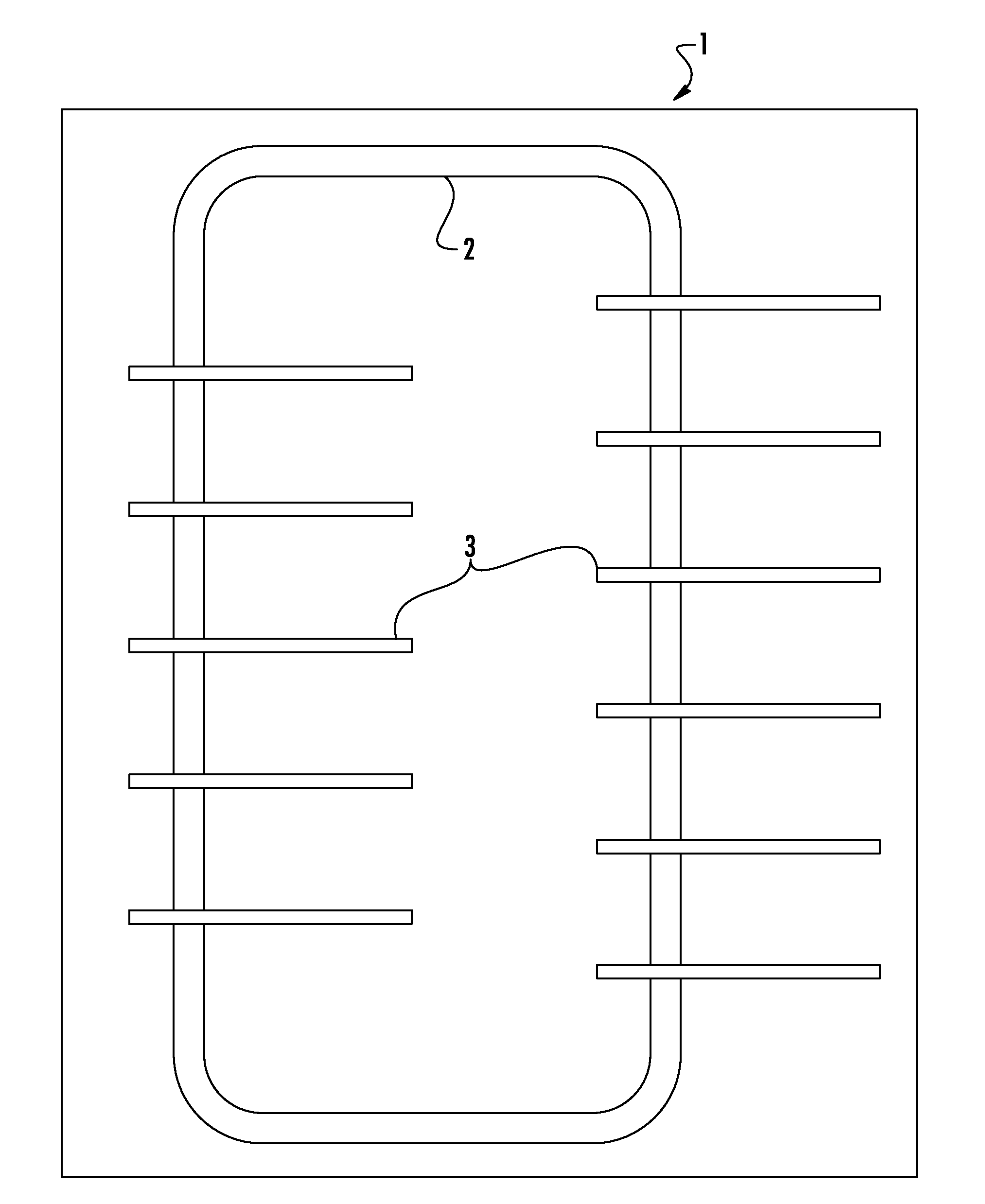
[0036]An embodiment depicted in FIG. 6 shows the block of building material 1 containing a magnetic circuit 2 and sensing devices 3 of at least one physical characteristic of the building material, wherein these sensing devices 3 are magnetically coupled to the magnetic circuit 2. The magnetic circuit 2 may be wholly buried in the building material 1, as shown in FIG. 6, or only be partially buried, as will be illustrated hereinafter.

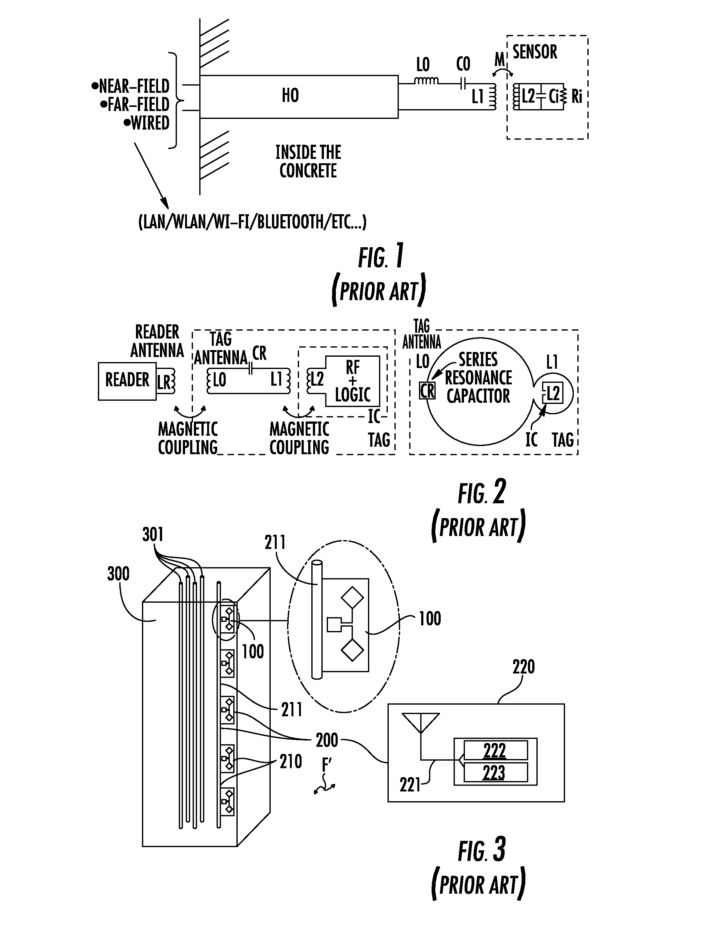
[0037]Sensing devices 3 adapted to be buried in a block of building material, such as, for example, the ones disclosed in the Italian patent application ITMI20102365 or the PCT patent application WO2012 / 084295 in the name of the same applicant and shown in FIG. 7, are magnetically coupled with the magnetic circuit 2. By inducing a variable magnetic field throughout the magnetic circuit 2, the circuit for power supplying and for contactless communications 4 generates an induced supply voltage of the sensor IC 5, that may operate also without electric con...


PUM

PropertyMeasurementUnit
thicknessaaaaaaaaaa
thicknessaaaaaaaaaa
thicknessaaaaaaaaaa

Abstract

A building structure includes a block of building material and a magnetic circuit buried in the block of building material. The structure also includes a plurality of sensing devices buried in the block of building material. Each sensing device may include a contactless power supplying circuit magnetically coupled with the magnetic circuit to generate a supply voltage when the magnetic circuit is subject to a variable magnetic field.

Description

FIELD OF THE INVENTION [0001]This invention relates to monitoring devices in building structures, and, more particularly, to a block made of a building material comprising a magnetic circuit to which sensing devices of at least one physical characteristic of the building material are magnetically coupled.BACKGROUND OF THE INVENTION[0002]The strategy for implementing damage detection and the characterization of mechanical structures is commonly called Structural Health Monitoring (SHM). Damages are defined as modifications of the material and / or of the geometrical properties of a structural system, comprising modifications of boundary conditions and connections of the system, that worsen performance of the system. The SHM process implies the observation of the mechanical system along the time using periodically:[0003]measurements of dynamic responses coming from an array of sensors,[0004]extraction of data of damage characteristics sensed from these measurements, and[0005]statistical...

Claims


Application Information

Patent Timeline
Patent Type & Authority Applications(United States)
IPC IPC(8): G01N27/72
CPCG01N27/72G01N27/82G01N33/381G01N33/383Y10T29/49018Y10T29/4902
Inventor PAGANI, ALBERTO
Owner STMICROELECTRONICS INT NV
Why Eureka
Try Eureka