Interface detection

a technology of interface detection and approximation function, applied in the field of interface detection, can solve the problems of inability to detect the interface, inability to predict the reduction of the reduced amplitude of the reflected signal, so as to improve the accuracy of the determination of the level of the interface, the effect of improving the accuracy of the approximation function

Active Publication Date: 2014-03-27
ROSEMOUNT TANK RADAR
View PDF2 Cites 12 Cited by
  • Summary
  • Abstract
  • Description
  • Claims
  • Application Information

AI Technical Summary

Benefits of technology

[0019]A further advantage of the present invention is that it is not required to know the properties, such as the dielectric constant, of the materials on either side of the interface. On the contrary, the propagation properties of the materials may also be determined by the method according to embodiments of the present invention. Furthermore, more than one interface may be detected.
[0020]The space between the tank roof and the uppermost surface of the product in the tank is generally filled with some kind of atmosphere which generally has a dielectric constant close to 1. Some liquids with strong evaporation, gases under pressure or water vapor at high temperature and pressure may have a dielectric constant clearly different from 1. Some applications may include liquid over the full tank dept but with an interface which is to be measured. Obviously, the method according to various embodiments of the invention would automatically adapt to such conditions even if the surface would be difficult to measure directly due to boiling, foam etc.
[0021]According to one embodiment of the invention, each of the first approximation function and the second approximation function is determined based on the relation between the electrical distance values and the physical distances for at least three reference impedance transitions. By increasing the number of reflected signals from reference impedance transitions used for determining the approximation functions, the accuracy in the determination of the approximation function can be improved, thereby improving the

Problems solved by technology

An extended interface may lead to an unpredictable reduction of amplitude of the reflected signal as it propagates through the interface.
Consequently, a diffuse interface may result in a reflected signal which is reduced in amplitude or otherwise distorted to the extent that it is no longer possible to detect the interface.
Furthermore,

Method used


Image

  • Interface detection
  • Interface detection
  • Interface detection

Examples


Embodiment Construction

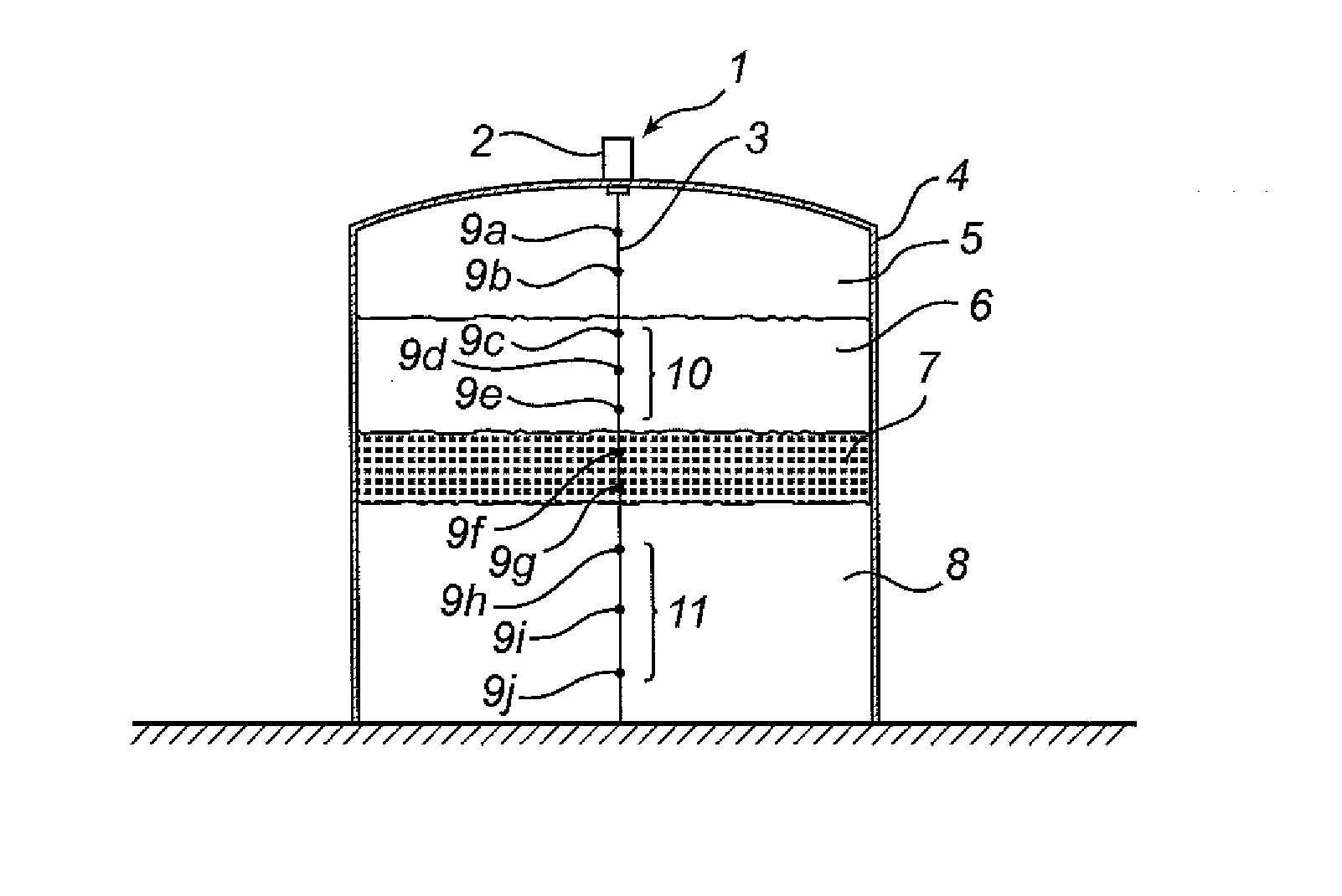
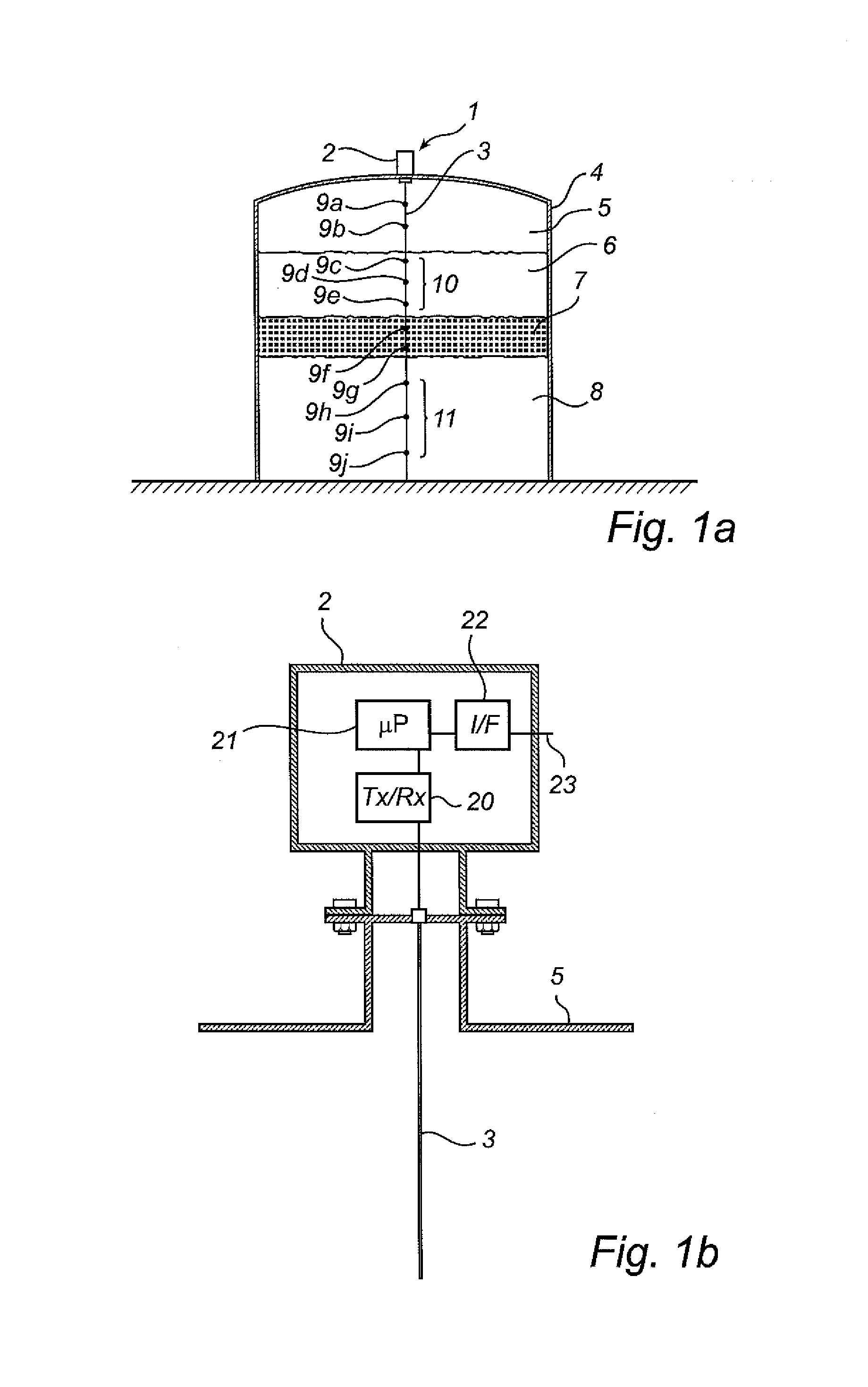
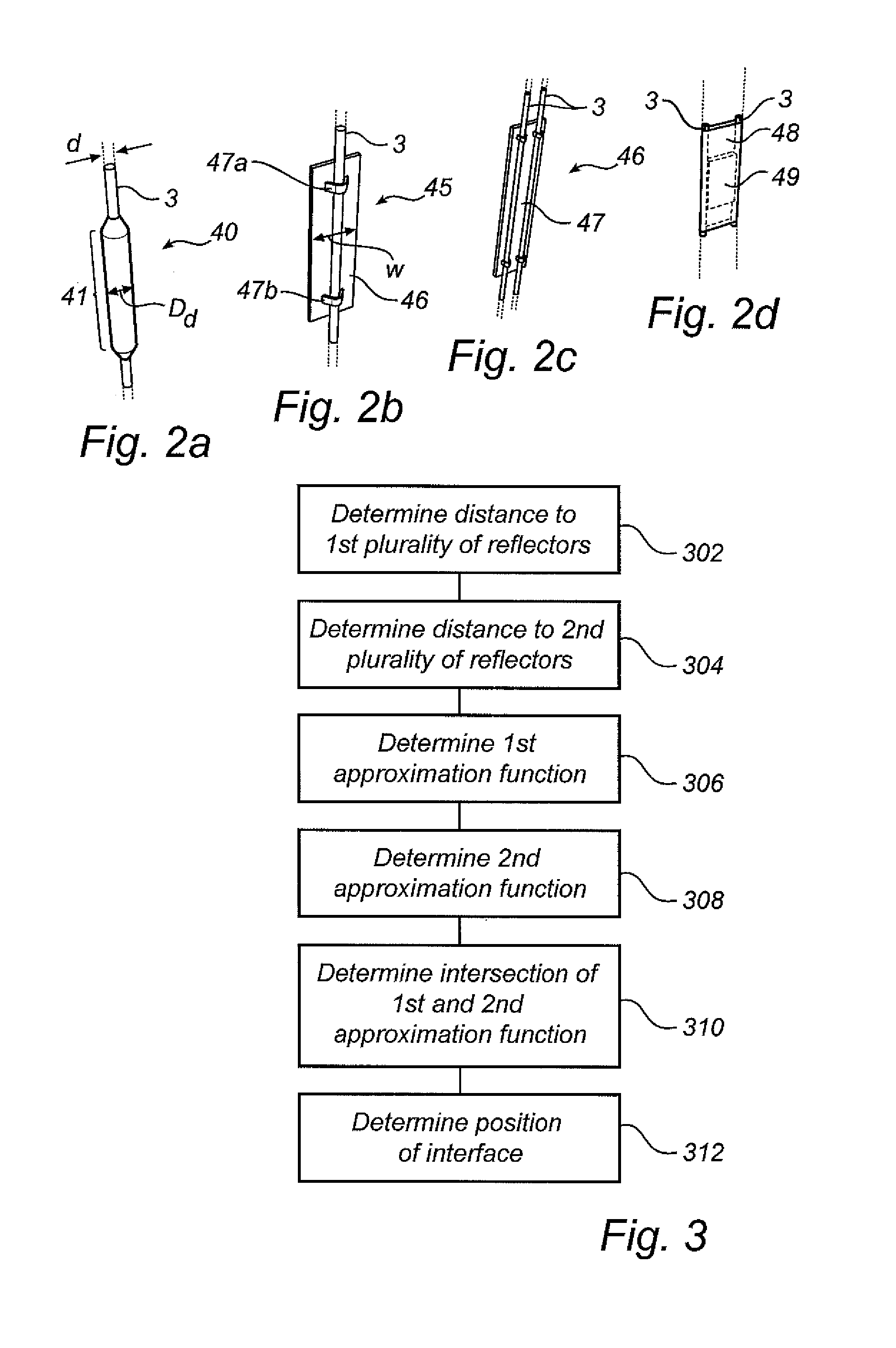
[0043]In the present detailed description, various embodiments of the method and the radar level gauge system for determining the level of an interface according to the present invention are mainly discussed with reference to a radar level gauge system having a twin line probe comprising a plurality of reference reflectors.

[0044]FIG. 1a schematically illustrates a radar level gauge system 1 according to an embodiment of the present invention, comprising a measurement electronics unit 2, and a probe 3 having a plurality of reference reflectors 9a-j. The radar level gauge system 1 is provided on a tank 4, which is partly filled with a product to be gauged. The tank contains a tank atmosphere 5, a first material 6, a second material 8 and an interface 7 between the two materials. By analyzing transmitted signals being guided by the probe 3 into the first material 6, through the material interface 7 and into the second material 8, the measurement electronics unit 2 can determine the dis...


PUM


Abstract

The invention relates to a method for determining a level of a material interface in a tank, by means of a radar level gauge system comprising a transceiver; a probe for guiding a transmitted electromagnetic signal towards the material interface. The probe comprises a first plurality of reference impedance transitions located above the interface at known physical distances from a reference position, and a second plurality of reference impedance transitions located below the interface at known physical distances from the reference position. The method comprising determining electrical distances to the first and second plurality of reference impedance transitions based on a signal reflected by the reference impedance transition, determining, a first and a second approximation function relating the first and second sets of electrical distance values to the physical distances; and determining the level of the material interface based on the first approximation function and the second approximation function.

Description

FIELD OF THE INVENTION[0001]The present invention relates to a method for determining a position of an interface in a product contained in a tank by means of a radar level gauge system.TECHNICAL BACKGROUND[0002]Radar level gauge systems are in wide use for measuring process variables of a product contained in a tank, such as filling level, temperature, pressure etc. Radar level gauging is generally performed either by means of non-contact measurement, whereby electromagnetic signals are radiated towards the product contained in the tank, or by means of contact measurement, often referred to as guided wave radar (GWR), whereby electromagnetic signals are guided towards and into the product by a probe acting as a waveguide. The probe is generally arranged vertically from top to bottom of the tank. The electromagnetic signals are subsequently reflected at the surface of the product, and the reflected signals are received by a receiver or transceiver comprised in the radar level gauge s...

Claims


Application Information

Patent Timeline
IPC IPC(8): G01R27/06
CPCG01F23/284
Inventor EDVARDSSON, OLOV
Owner ROSEMOUNT TANK RADAR
Why Eureka
Try Eureka