Power Converter

a power converter and converter technology, applied in the direction of electric devices, propulsion by batteries/cells, transportation and packaging, etc., can solve the problems of frequent different degrees of emergency, and achieve the effect of high safety and quick performan

Active Publication Date: 2014-04-03
HITACHI ASTEMO LTD
View PDF10 Cites 86 Cited by
  • Summary
  • Abstract
  • Description
  • Claims
  • Application Information

AI Technical Summary

Benefits of technology

[0035]The power converter including the protection circuit according to the invention is capable of quickly performing an optimum protection control operation of the system including the power converter with high safety according to a failure situation of the power converter.

Problems solved by technology

Further, when the electrical motor is driven, the degree of emergency is frequently different between the case of an over current and the case of an over voltage.

Method used


Image

  • Power Converter
  • Power Converter
  • Power Converter

Examples


Embodiment Construction

[0045]Hereinafter, an embodiment of the present invention will be described with reference to FIGS. 1 to 9 giving an example in which the invention is applied to a hybrid vehicle electrical motor driving device.

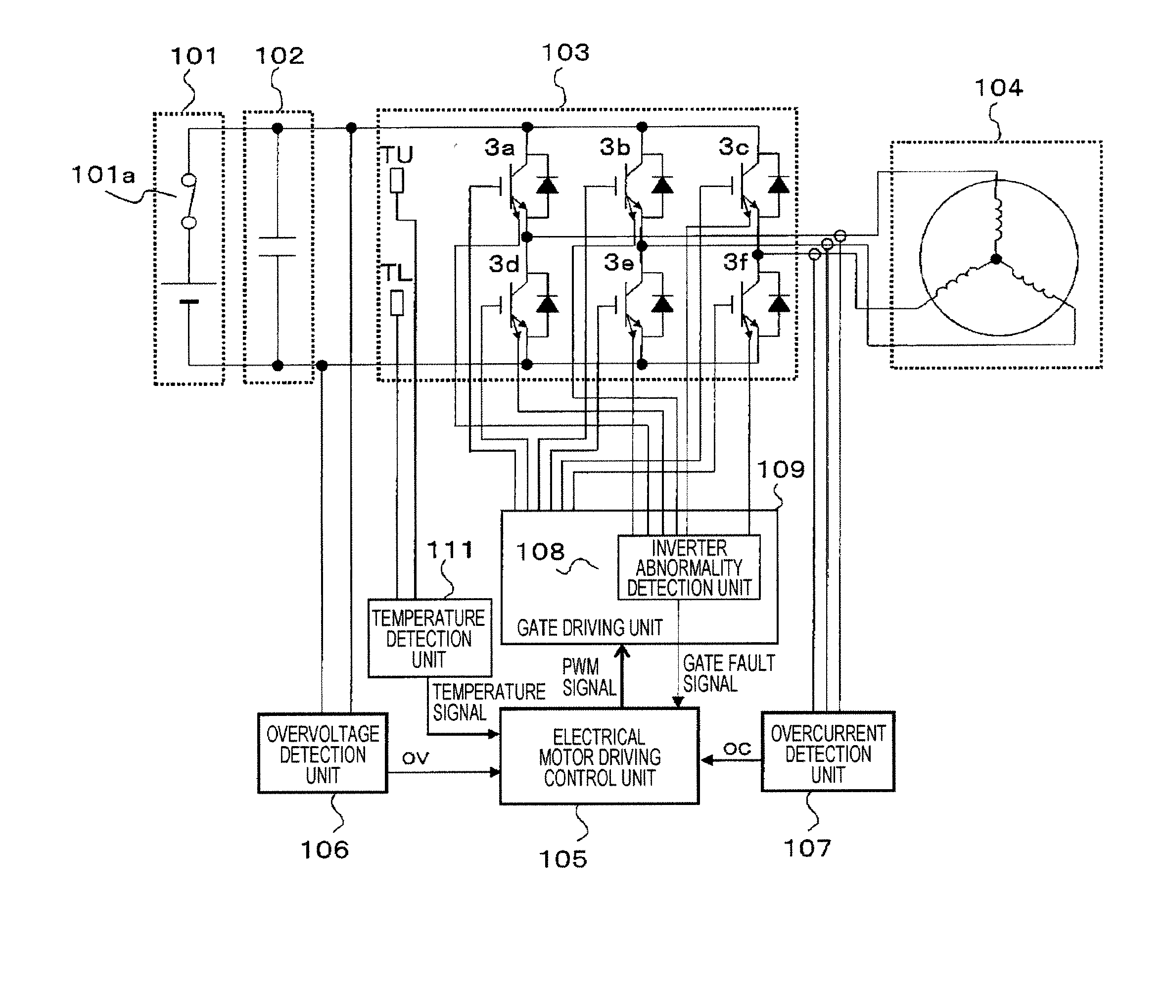
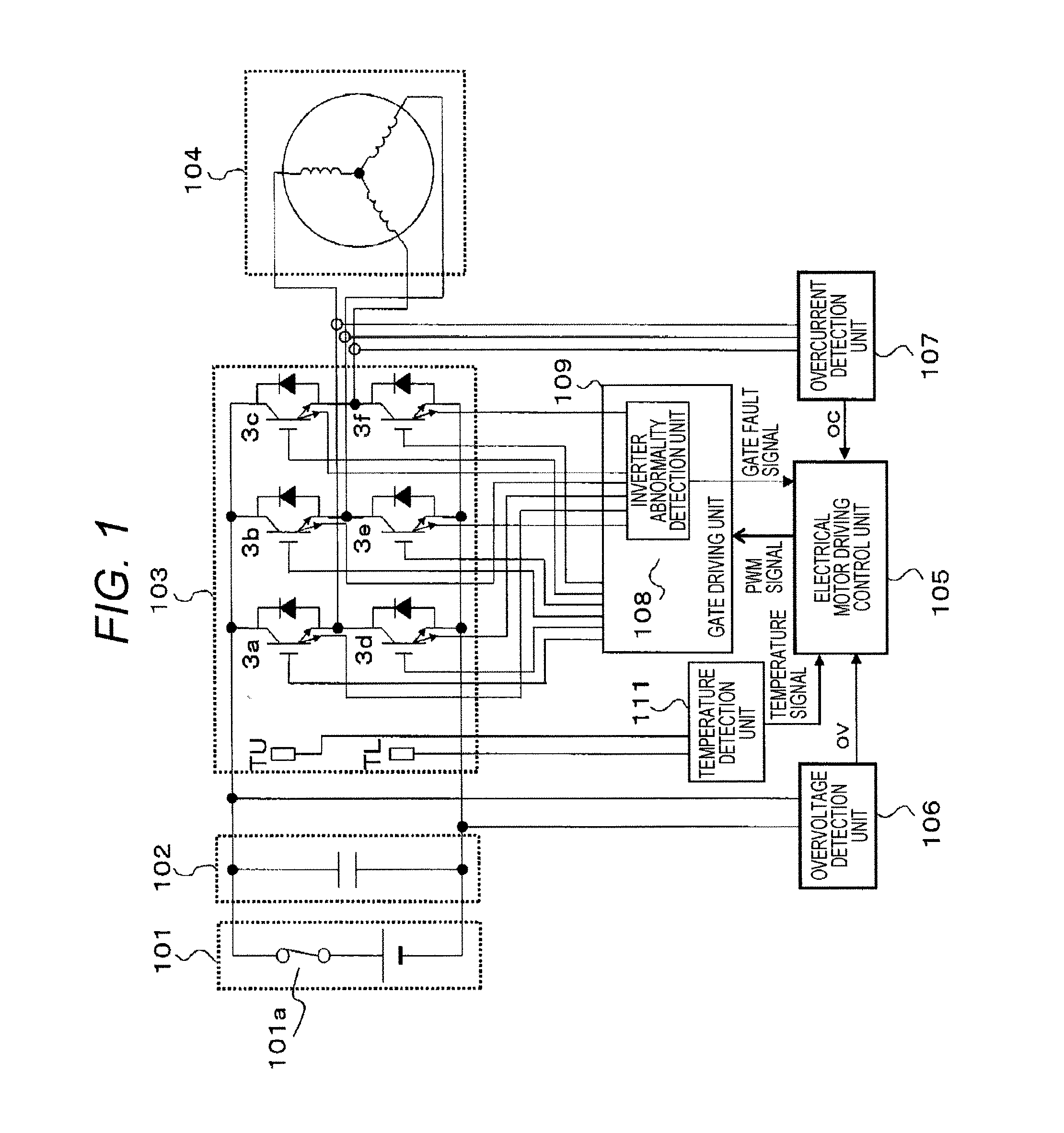
[0046]FIG. 1 is a diagram illustrating an example of a power conversion circuit when the invention is applied to the hybrid vehicle electrical motor driving device. In FIG. 1, reference numeral 101 denotes a DC power source, reference numeral 102 denotes a smoothing capacitor, reference numeral 103 denotes an inverter unit, reference numeral 104 denotes an electrical motor, reference numeral 105 denotes an electrical motor driving control unit, reference numeral 106 denotes an over voltage detection unit, reference numeral 107 denotes an over current detection unit, reference numeral 108 denotes an inverter abnormality detection unit, reference numeral 109 denotes a gate driving unit, and reference numeral 111 denotes a temperature detection unit. The smoothing capacitor 102 ...


PUM


Abstract

A power converter includes an inverter unit that includes a plurality of semiconductor switching elements constituting upper and lower arms and converts DC power into AC power; a gate driving unit that outputs, to the inverter unit, a gate signal used to drive gates of the plurality of semiconductor switching elements; a driving control unit that supplies the gate driving unit with a switching control signal used for the gate driving unit to output the gate signal; a first abnormality detection unit that performs over voltage detection of the DC power and over current detection of the AC power and temperature detection of the upper and lower arms; and a second abnormality detection unit that detects abnormality of the plurality of semiconductor switching elements of the upper arm and lower arms, wherein the driving control unit includes a first protection circuit and a second protection circuit.

Description

TECHNICAL FIELD[0001]The present invention relates to a power converter that includes an inverter using a semiconductor switching element, and more particularly, to a power converter that includes a protection circuit.BACKGROUND ART[0002]There is a known device that performs power conversion by an inverter circuit including a semiconductor switching element, supplies power to a load, and includes a plurality of protection circuits such as over current protection circuits or over voltage protection circuits (for example, see PTL 1). PTL 1 discloses a technology for performing control such that an operation is stopped by urgently stopping an operation of the semiconductor switching element of the inverter circuit at the time of a major failure such as an over current or an over voltage and by slowly decreasing a current flowing in the semiconductor switching element at the time of a minor failure such as overload. That is, the semiconductor switching element enters an open state in wh...

Claims


Application Information

Patent Timeline
Patent Type & Authority Applications(United States)
IPC IPC(8): H02H7/122
CPCH02H7/122B60L3/003H02M1/32H02P27/08B60L15/007B60L50/51Y02T10/64Y02T10/70H02M1/327
Inventor IGARASHI, HIROAKISHIGETA, SATORUOGURA, TAKASHI
Owner HITACHI ASTEMO LTD
Why Eureka
Try Eureka