Belt finishing device, belt finishing system and method for producing a belt finishing device

a belt finishing and belt technology, applied in the direction of superfinishing machines, grinding machines, metal-working apparatuses, etc., can solve the problems that the above requirements cannot be optimally met with the conventional belt finishing devices, and achieve the effect of reducing pressing force, reducing pressing force, and easy control

Active Publication Date: 2014-04-03
SUPFINA GRIESHABER GMBH & CO KG
View PDF16 Cites 8 Cited by
  • Summary
  • Abstract
  • Description
  • Claims
  • Application Information

AI Technical Summary

Benefits of technology

[0026]The pressing forces that can be transferred by the pressure belt to the finishing belt in the width direction of the finishing belt may be more easily controlled when the pressure belt is formed as an endless belt. Such pressure belt has a front active section whose front end interacts with the back side of the finish belt. Such endless belt is deflected in the region of spaced-apart bearing surfaces and transitions into a rear section that is spaced from the finishing belt.
[0027]According to another advantageous feature of the present invention, a rear section of the pressure belt may be supported or is supported by a pressure belt-support device. This creates another possibility for influencing the tension of the pressure belt along the width of the finishing belt.
[0028]According to another aspect of the invention, a belt finishing system includes an aforedescribed belt finishing device and a workpiece with a workpiece surface to be machined. At least one of the bearing surfaces and / or the pressure belt has at least one discontinuity, wherein the workpiece surface is also discontinuous in the region of a bore and wherein the position of the discontinuity is aligned with the position of the hole in the width direction of the finishing belt. Such belt finishing system is capable of producing crankshafts or camshafts that have a bore, in particular an oil outlet bore in the bearing surface. A plane of rotation associated with such bore experiences lower pressing forces during the finish-machining of the workpiece surface, so that the finishing belt presses with a lower pressing force against the workpiece in the region of the edge of the bore than in the laterally adjacent regions. This can prevent the finishing belt from penetrating too deeply into the bore and thus remove an excessive quantity of material in the region of the edge of the bore. Advantageously, a workpiece section that is already mechanically weakened in the region of the bore is then not further weakened, so that, in spite of such a bore, bearing surfaces having a comparatively high support surface proportion may be produced.

Problems solved by technology

It has been observed that the above requirements cannot be optimally met with the conventional belt finishing devices.

Method used


Image

  • Belt finishing device, belt finishing system and method for producing a belt finishing device
  • Belt finishing device, belt finishing system and method for producing a belt finishing device
  • Belt finishing device, belt finishing system and method for producing a belt finishing device

Examples


Embodiment Construction

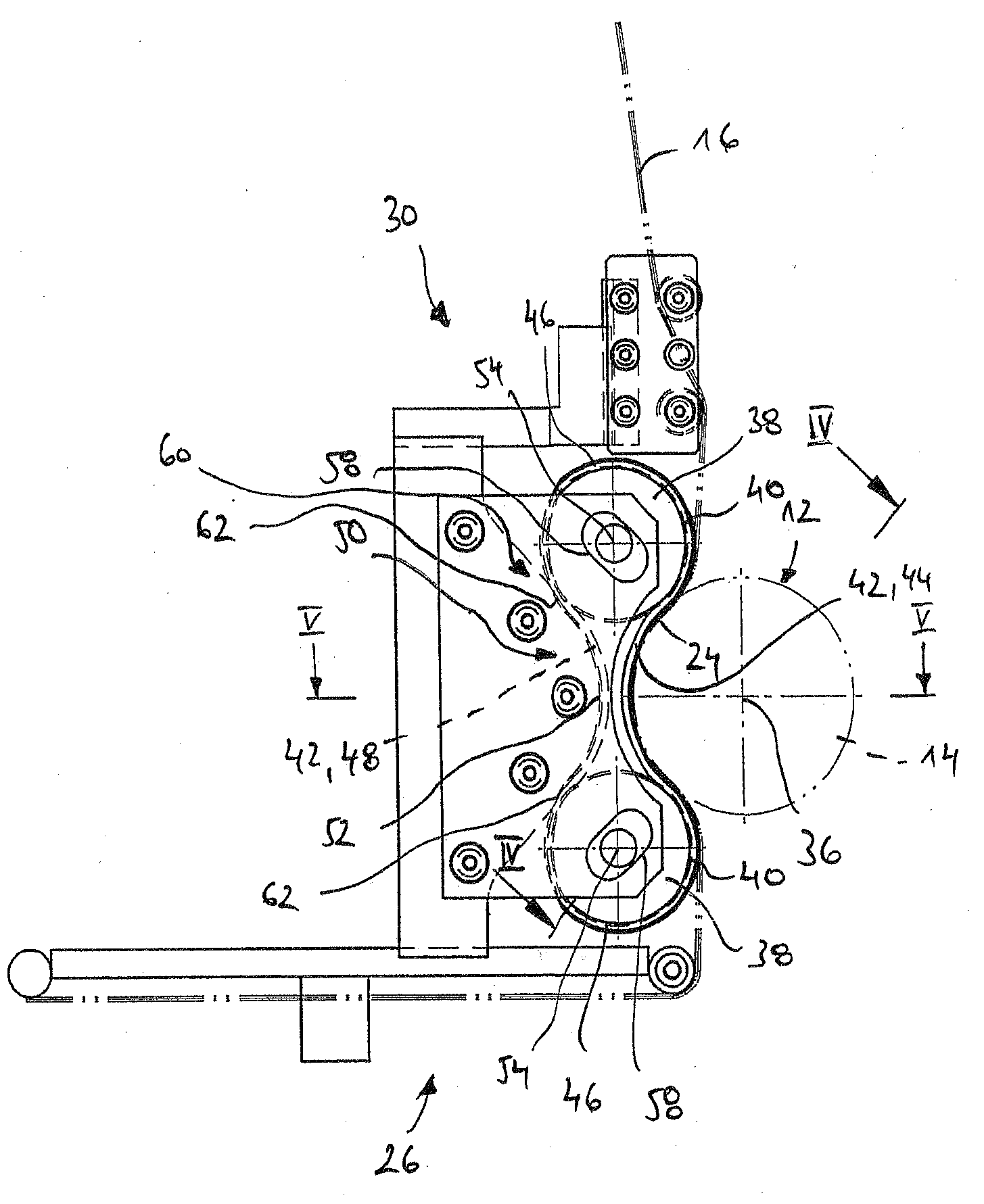
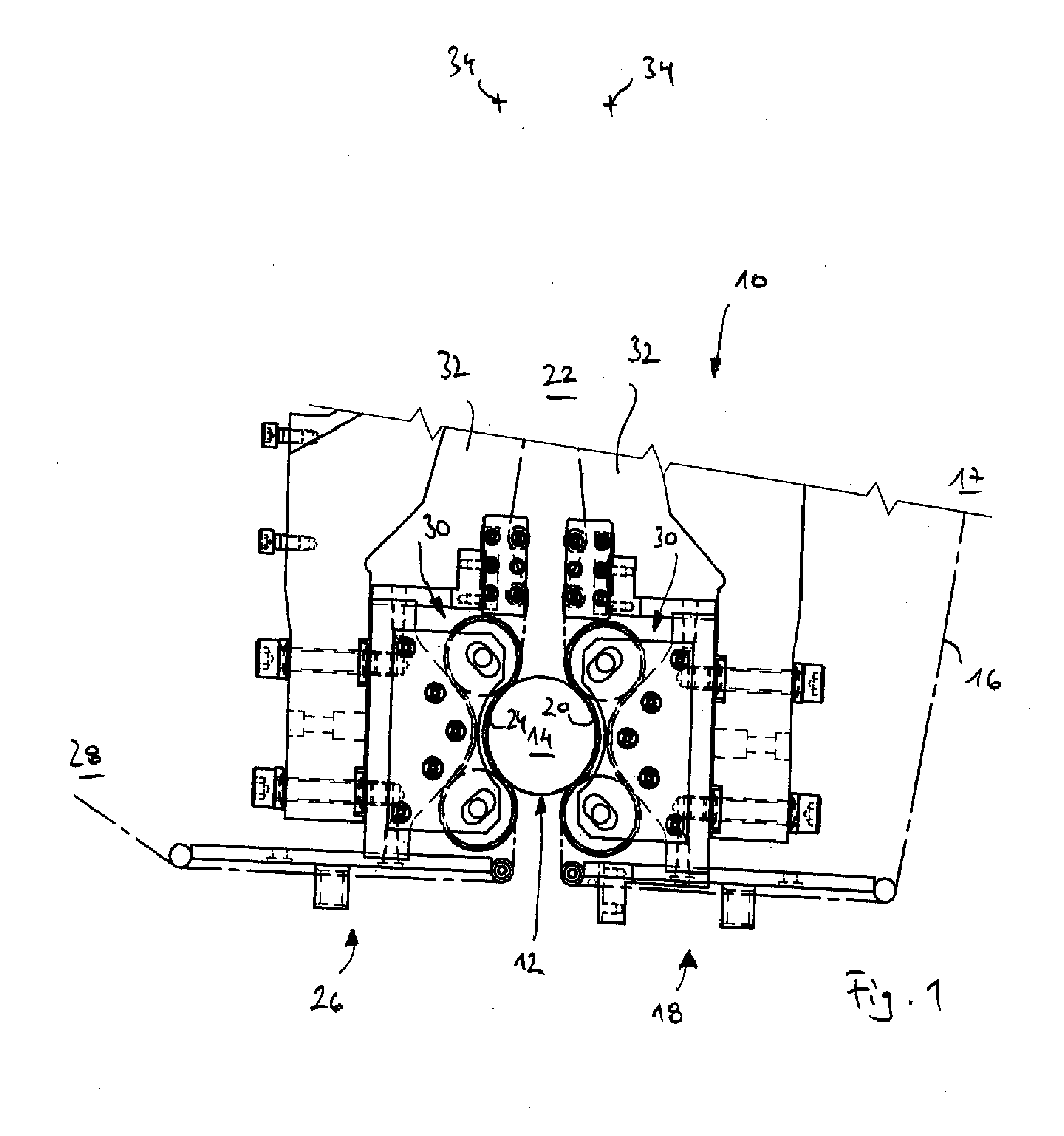
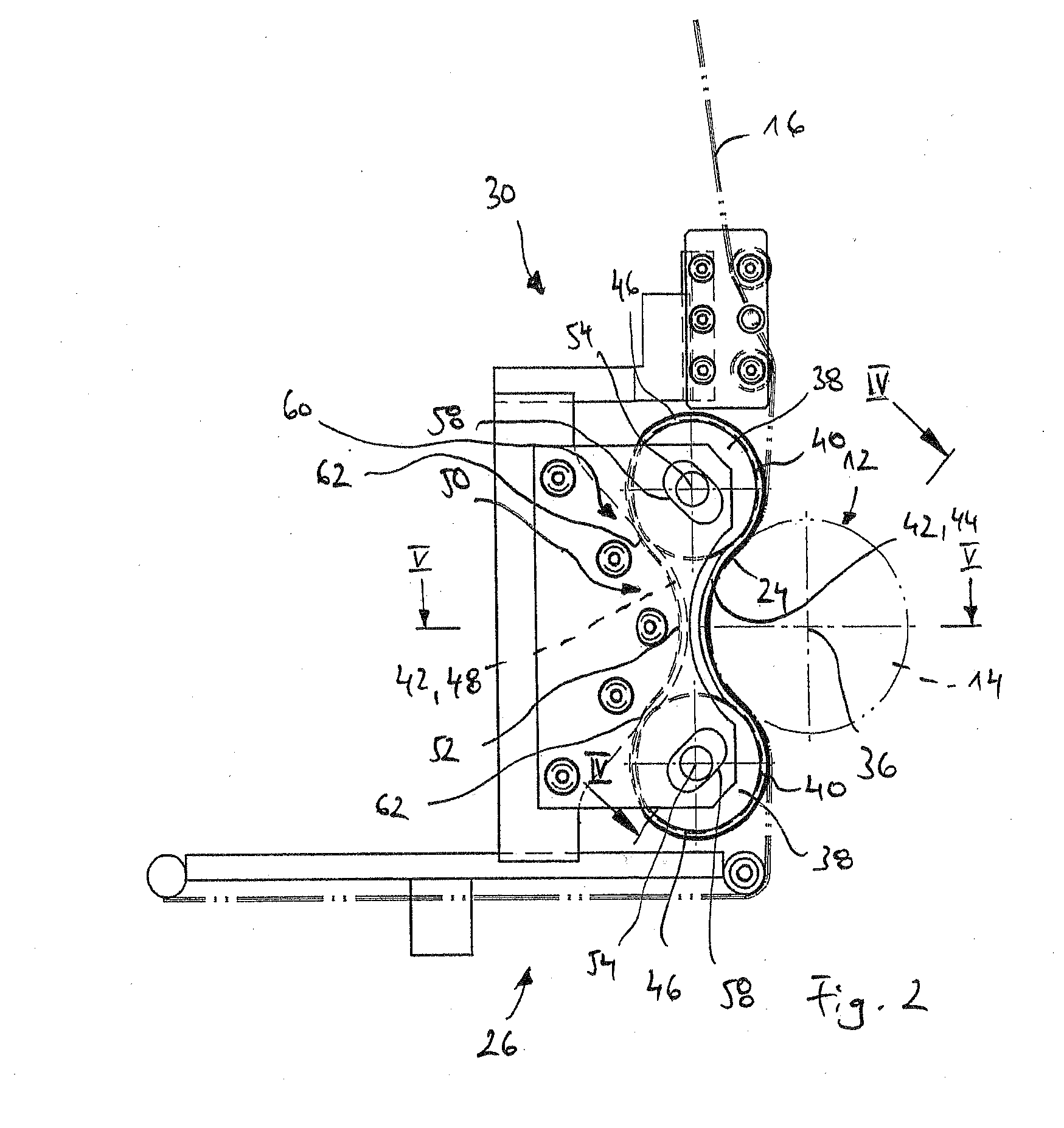
[0073]Throughout all the figures, same or corresponding elements may generally be indicated by same reference numerals. These depicted embodiments are to be understood as illustrative of the invention and not as limiting in any way. It should also be understood that the figures are not necessarily to scale and that the embodiments are sometimes illustrated by graphic symbols, phantom lines, diagrammatic representations and fragmentary views. In certain instances, details which are not necessary for an understanding of the present invention or which render other details difficult to perceive may have been omitted.

[0074]Turning now to the drawing, and in particular to FIG. 1, there is shown a belt finishing device designated by the reference numeral 10. The belt finishing device is used for finish-machining an in particular rotationally symmetrical workpiece surface 12 of a workpiece 14. The workpiece surface 12 is finish-machined with a finishing belt 16.

[0075]A reservoir 17 is, for ...


PUM

PropertyMeasurementUnit
wrap angleaaaaaaaaaa
heightaaaaaaaaaa
widthaaaaaaaaaa

Abstract

A belt finishing device includes a finishing belt, two bearing surfaces that are spaced-apart in a running direction of the finishing belt, and a pressing device for pressing the finishing belt against a workpiece surface. The pressing device has a pressure belt that is supported on the two spaced-apart bearing surfaces. At least one of a bearing surface and the pressure belt have a profile that deviates in a width direction of the finishing belt from a straight course.

Description

CROSS-REFERENCES TO RELATED APPLICATIONS[0001]This application claims the priority of European Patent Application EP 12 186 775.8, filed Oct. 1, 2012, pursuant to 35 U.S.C. 119(a)-(d), the content of which is incorporated herein by reference in its entirety as if fully set forth herein.BACKGROUND OF THE INVENTION[0002]The present invention relates to a belt finishing device with a pressing mechanism for pressing a finishing belt against a workpiece surface.[0003]The following discussion of related art is provided to assist the reader in understanding the advantages of the invention, and is not to be construed as an admission that this related art is prior art to this invention.[0004]In finish-machining, the workpiece surface to be machined is rotatably driven and relative movement between the workpiece and the finishing belt parallel to the workpiece axis is superimposed on this rotary motion. In this way, the workpiece surface is provided with a cross-cut structure characteristic f...

Claims


Application Information

Patent Timeline
Patent Type & Authority Applications(United States)
IPC IPC(8): B24B21/20
CPCB24B21/20B24B21/02B24B35/00B24B21/06B24B21/08Y10T29/49B24B21/18
Inventor HILDEBRANDT, OLIVERWOLBER, SIMON
Owner SUPFINA GRIESHABER GMBH & CO KG
Why Eureka
Try Eureka