Cooling for Combustor Liners with Accelerating Channels

a technology of accelerating channels and combustor liners, which is applied in the direction of efficient propulsion technologies, machines/engines, light and heating apparatus, etc., can solve the problems of entrainment of cooling flow in the outer recirculation zone, and achieve the effect of preventing cross flow degradation

Active Publication Date: 2014-04-10
RTX CORP
View PDF3 Cites 40 Cited by
  • Summary
  • Abstract
  • Description
  • Claims
  • Application Information

AI Technical Summary

Benefits of technology

[0025]In yet another refinement, the method may further include preventing cross flow degradation by incorporating a calming region between each cooling path, each cooling path may include at least an accelerating channel.

Problems solved by technology

However, aggressive tapering of the convergent combustion chamber section may cause entrainment of cooling flow in the outer recirculation zone.

Method used


Image

  • Cooling for Combustor Liners with Accelerating Channels
  • Cooling for Combustor Liners with Accelerating Channels
  • Cooling for Combustor Liners with Accelerating Channels

Examples


Embodiment Construction

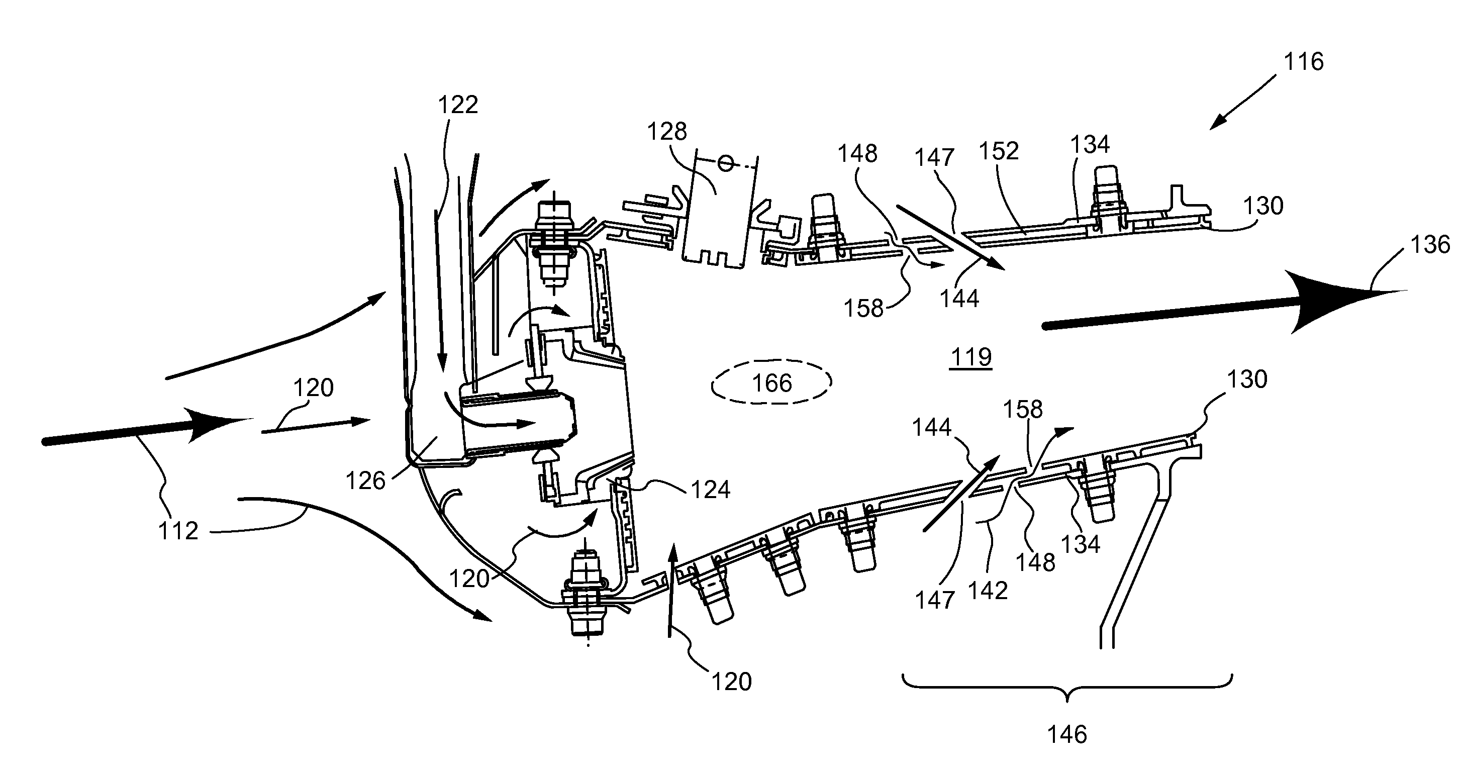
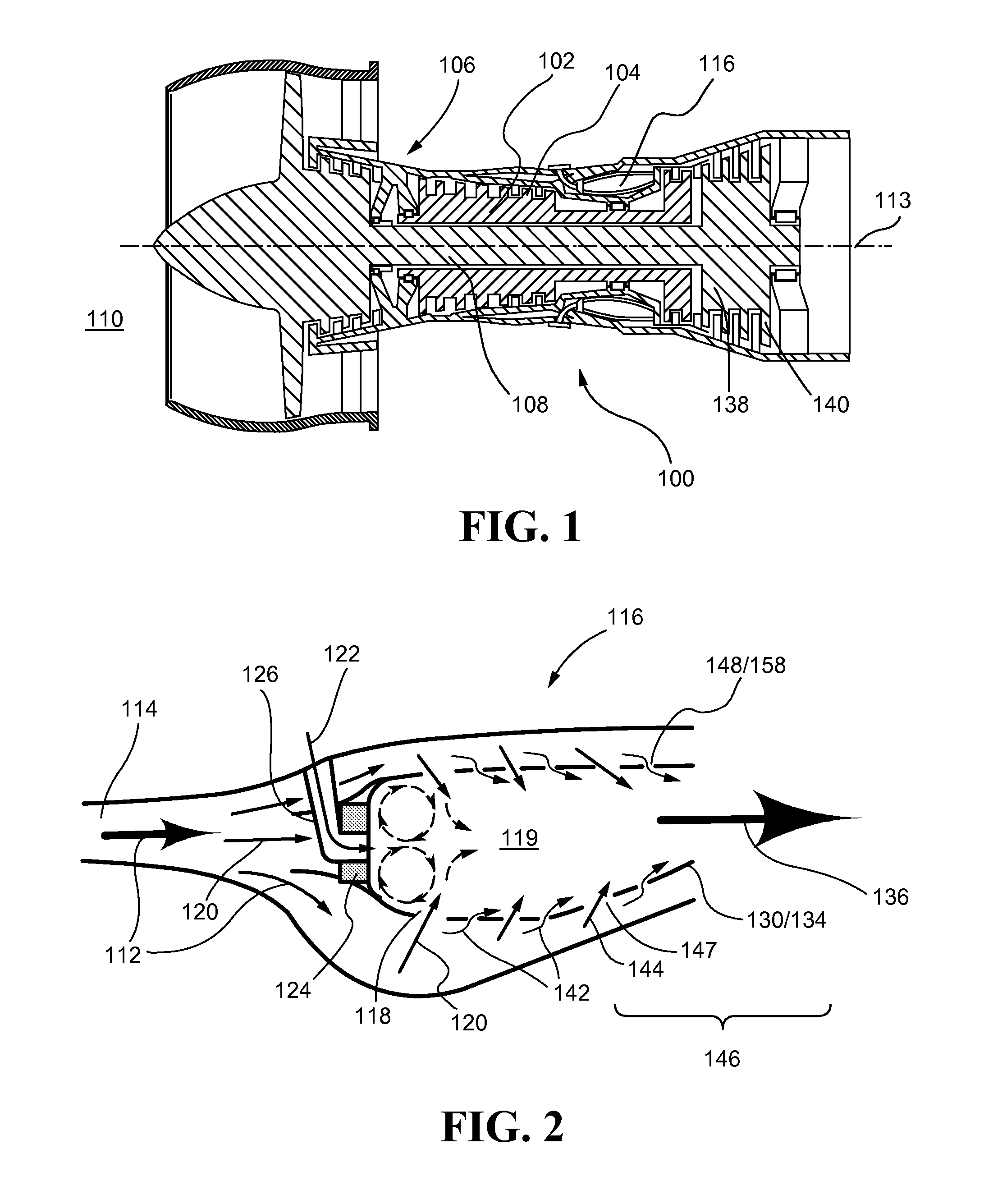
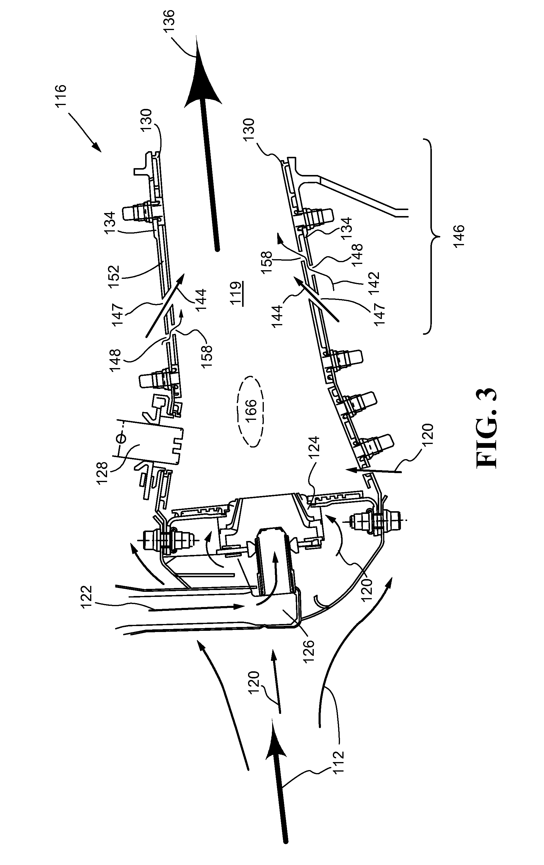
[0038]Referring now to the drawings, and with specific reference to FIG. 1, a gas turbine engine, generally referred to by numeral 100, is disclosed. The gas turbine engine 100 may have a compressor 102 with a plurality of blades 104 positioned at a forward end 106 of the engine 100. The compressor 102 may further be connected to a rotating shaft 108. When the compressor 102 rotates, it draws ambient air 110 into the engine 100, and compresses same into compressed air 112. The compressed air 112 may be forced through a diffuser 114, as shown in FIG. 2, to a combustor 116. At the combustor 116, the compressed air 112 may be split to be used in multiple ways.

[0039]Referring now to FIG. 2 and FIG. 3, at the combustor 116 some of the compressed air 112 may pass through a plurality of air admittance holes 118 into a combustion chamber 119 as combustion air 120. The combustion air 120 may be mixed with a fuel 122 by a swirler 124. The fuel 122 may enter the combustion chamber 119 by a fue...


PUM


Abstract

A combustor liner which reduces cooling flow to a combustion chamber and augments pressure drop split between impingement holes and effusion holes is disclosed. The combustor liner may further include accelerating channels, trip strips, pedestals, and cone-shaped effusion holes to provide further cooling of the liner. The combustor liner may reduce NOx production and the temperature of the combustion chamber of a gas turbine engine or the like.

Description

FIELD OF THE DISCLOSURE[0001]The present disclosure generally relates to gas turbine engines and, more specifically, to cooling of combustors of gas turbine engines.BACKGROUND OF THE DISCLOSURE[0002]A gas turbine engine, typically used as a source of propulsion in aircraft, operates by drawing in ambient air, mixing and combusting that air with a fuel, and then directing the exhaust from the combustion process out of the engine. A compressor, with a plurality of blades, rotates to draw in and compress the ambient air. A portion of the compressed air is used to cool a combustor, while the rest is directed into the combustor, mixed with a fuel, and ignited.[0003]Typically an igniter generates an electrical spark to ignite the air-fuel mixture. The products of the combustion, NOx and CO, and the remains of the air-fuel mixture then travel out of the combustion chamber as exhaust and through a turbine. The turbine, having a plurality of blades extending from a central shaft, is forced t...

Claims


Application Information

Patent Timeline
Patent Type & Authority Applications(United States)
IPC IPC(8): F02C7/18F02C6/08
CPCF02C7/18F23R3/002F23R3/06F23R2900/03041F23R2900/03042F23R2900/03043F23R2900/03044F23R3/005F23R3/16F23R2900/03045Y02T50/60
Inventor CUNHA, FRANK J.SNYDER, TIMOTHY S.ERBAS-SEN, NURHAKWILLIAMS, ALEXANDER W.MULE, NICHOLASBANGERTER, JAMES P.
Owner RTX CORP
Why Eureka
Try Eureka