
Fiber bed assembly including a re-entrainment control device for a fiber bed mist eliminator

a technology of reentrainment control and fiber bed, which is applied in the direction of separation process, dispersed particle separation, chemistry apparatus and processes, etc., can solve the problems of unsatisfactory aerosol injection, undesirable exhaustion of certain aerosols to the environment, and fouling of downstream process equipmen

Active Publication Date: 2014-04-10
MECS
View PDF6 Cites 25 Cited by
  • Summary
  • Abstract
  • Description
  • Claims
  • Application Information

AI Technical Summary

Benefits of technology

The present invention is related to a fiber bed assembly for use in a mist eliminator to remove aerosols and soluble solids from a gas stream. The fiber bed assembly comprises a fiber bed support and a fiber bed which passes the gas stream through it. A re-entrainment control device is located downstream of the fiber bed and has a shape that changes the direction of the gas stream's flow path to separate aerosols and soluble solids from the gas stream by inertial force. The fiber bed assembly is designed to minimize re-entrainment of aerosols and soluble solids, which can occur when gas stream flows through a fiber bed. The technical effect of the invention is the improved removal of aerosols and soluble solids from gas streams.

Problems solved by technology

However the aerosol comes to be in the gas stream, it can be undesirable to inject the aerosol into other processing equipment because the aerosol may be corrosive or otherwise lead to damage or fouling of the processing equipment.
Moreover, it can be undesirable to exhaust certain aerosols to the environment.
Re-entrainment of collected liquid from the downstream surface of the fiber bed often causes problems.
These problems can include any of the following individually or in combination; fouling of downstream process equipment, degradation of product purity, corrosion to ductwork and in some cases difficulty in achieving emission requirements.
This problem is particularly severe at the bottom of a vertically disposed fiber bed since all of the liquid collected by the fiber bed necessarily drains to the bottom and from a practical standpoint because of gas phase drag on the liquid, out the downstream surface at the bottom of the fiber bed.
At this disengagement point where the greatest cumulative drainage occurs, gas phase drag can cause bubbling, “spitting”, jetting or fragmentation of the draining liquid.

Method used


Image

  • Fiber bed assembly including a re-entrainment control device for a fiber bed mist eliminator
  • Fiber bed assembly including a re-entrainment control device for a fiber bed mist eliminator
  • Fiber bed assembly including a re-entrainment control device for a fiber bed mist eliminator

Examples


Embodiment Construction

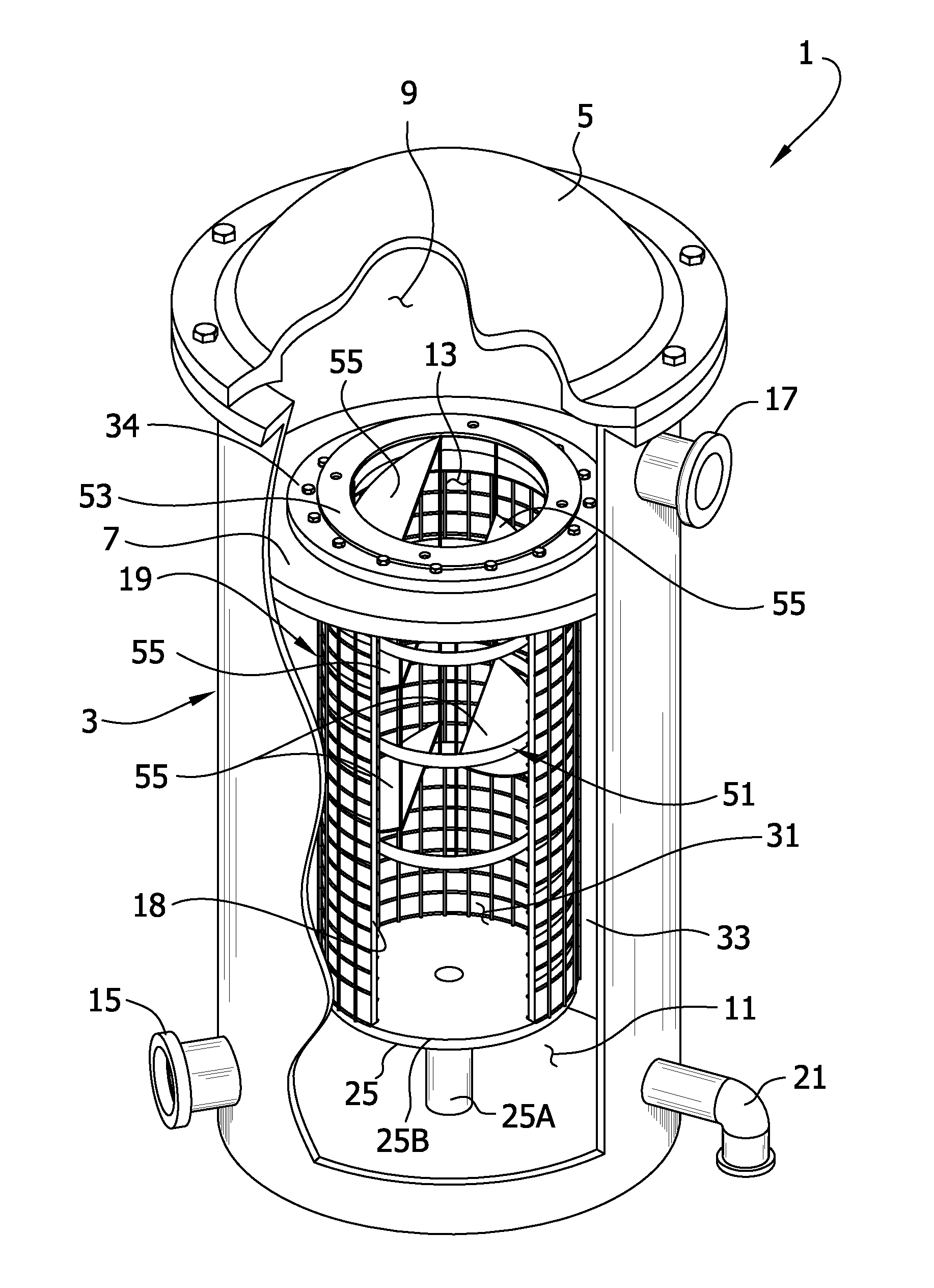
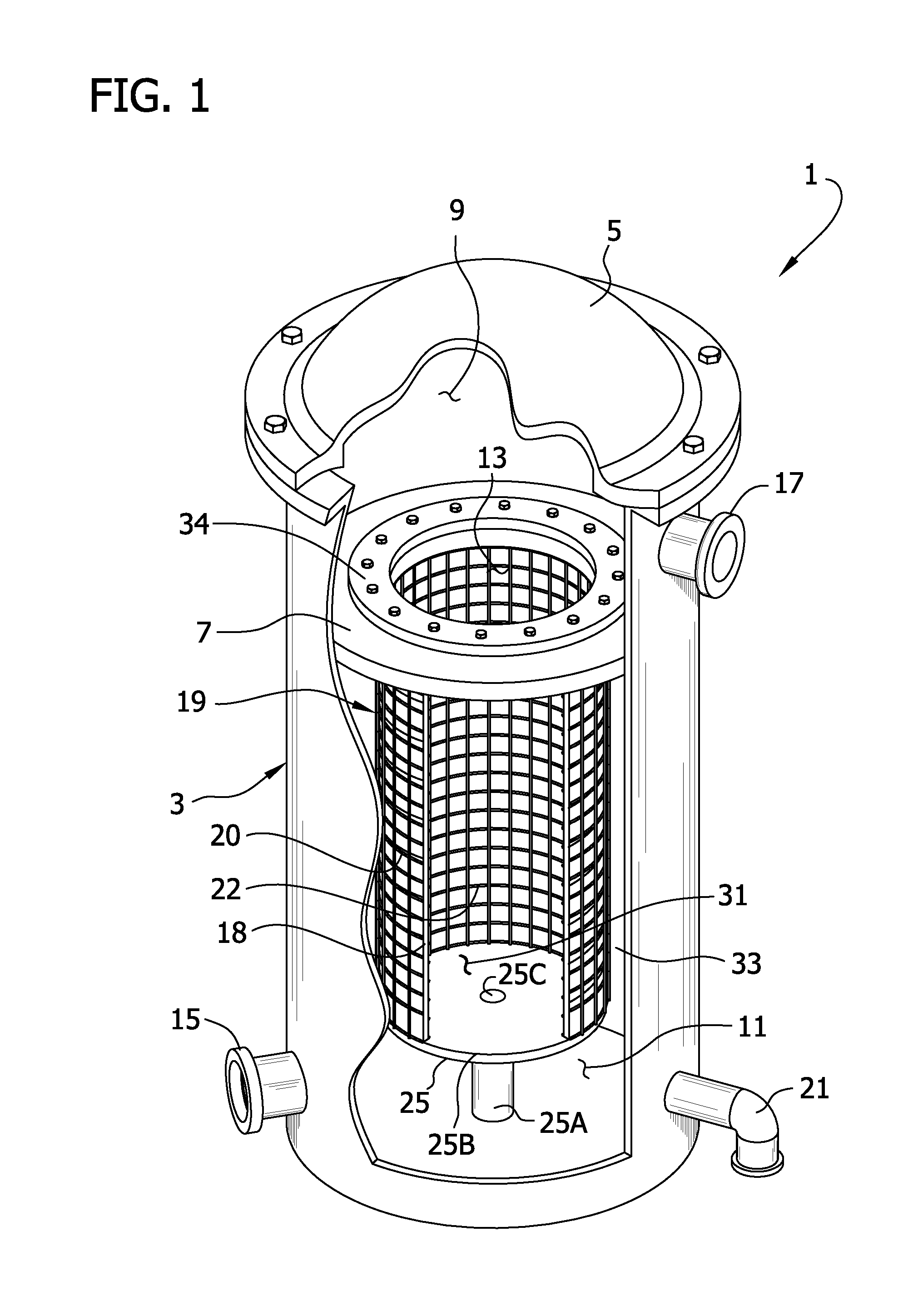
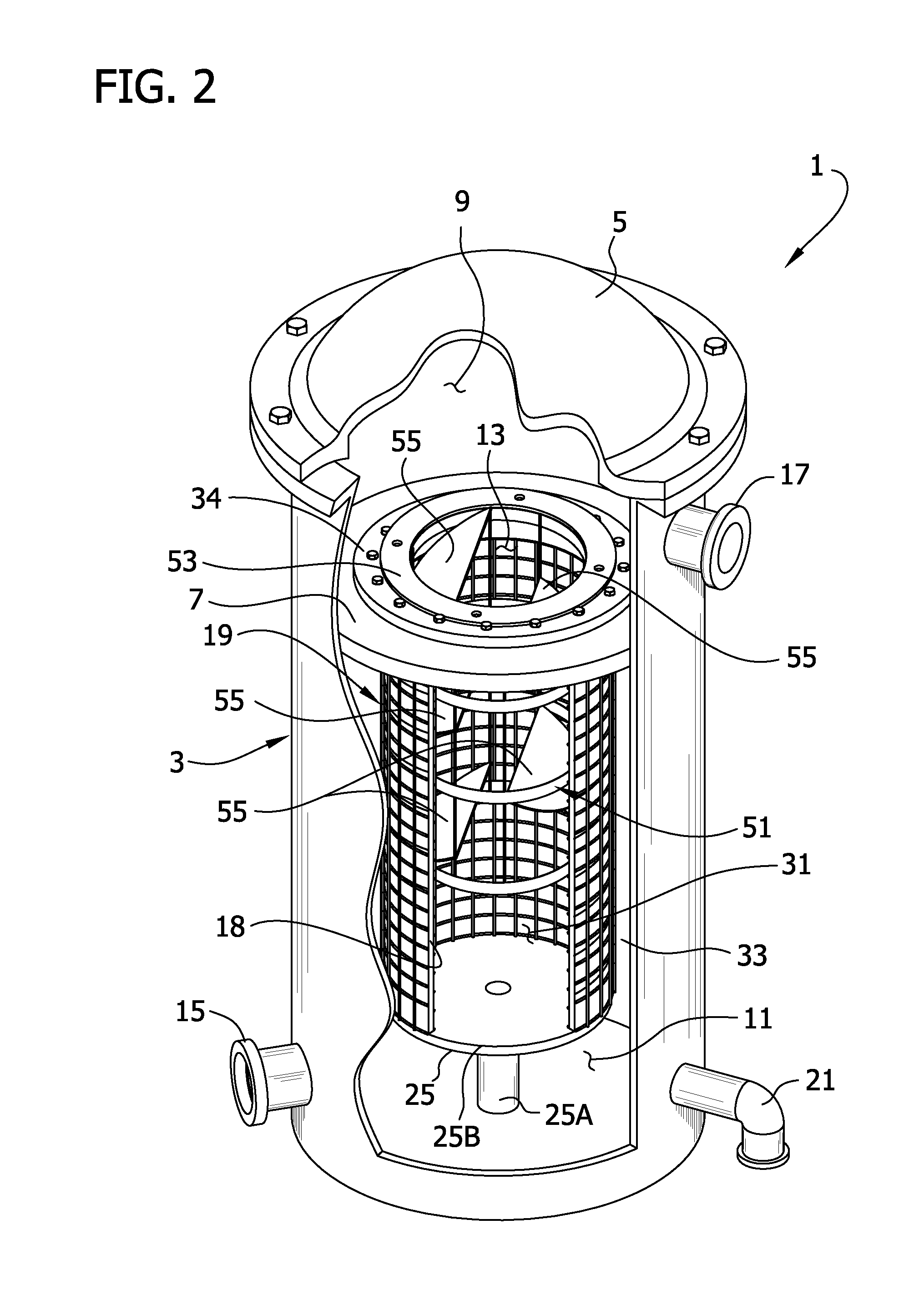
[0024]The present invention is directed to an improved fiber bed mist eliminator comprising a re-entrainment control device located on the downstream side of a fiber bed. The re-entrainment control device has a construction that causes the gas stream to have its average flow path redirected as it travels from the downstream surface of the fiber bed toward the outlet of the mist eliminator.

[0025]The mist eliminator of the present invention utilizes a fiber bed separator as the primary de-entrainment medium. Fiber beds are ideal for use in gas streams having a high liquid aerosol content, and are effective at removing a wide range of particulates of various sizes from the gas stream. Generally, as described above, a fiber bed acts to remove particulates from the gas stream in a suitable manner, such as through Brownian diffusion and impaction of those particulates onto its constituent fibers. Particulates captured by the fibers naturally drain downward through the fiber bed under the ...


PUM

PropertyMeasurementUnit
diameteraaaaaaaaaa
diameteraaaaaaaaaa
diameteraaaaaaaaaa

Abstract

A fiber bed assembly used to remove aerosols and / or wetted soluble solids from a moving gas stream includes a fiber bed support and a fiber bed supported by the fiber bed support so that the gas stream passes through the fiber bed moving from an upstream space to a downstream space with respect to the fiber bed. A re-entrainment control device is located within a downstream space defined by the fiber bed so that at least a portion of the gas stream passes through the re-entrainment control device. The re-entrainment control device is shaped to change the direction of the average flow path of the gas stream as the gas stream passes through the re-entrainment control device so as to cause aerosols and / or wettable solids contained therein to be separated from the gas stream by inertial force. A re-entrainment control device and method of use are also disclosed.

Description

FIELD OF THE INVENTION[0001]The present invention generally relates to a re-entrainment control device for use downstream from a fiber bed in a fiber bed mist eliminator.BACKGROUND OF THE INVENTION[0002]Fiber bed mist eliminators have wide industrial application in the removal of aerosols from gas streams. The generation of aerosols (“mist”) in gas streams is common in the course of manufacturing processes. Aerosols can be formed, for instance, as a result of mechanical forces (e.g., when a flow including a liquid runs into a structure) that atomize a liquid. Cooling of a gas stream may result in the condensation of vapor to form a mist, and chemical reactions of two or more gases may take place at temperatures and pressures where the reaction products are mists. However the aerosol comes to be in the gas stream, it can be undesirable to inject the aerosol into other processing equipment because the aerosol may be corrosive or otherwise lead to damage or fouling of the processing eq...

Claims


Application Information

Patent Timeline
Patent Type & Authority Applications(United States)
IPC IPC(8): B01D45/06B01D50/00
CPCB01D46/2403B01D46/0031B01D46/0049B01D46/30B01D46/003B01D50/20
Inventor AZWELL, DOUGLAS E.MUELLER, FREDERICK L.ZIEBOLD, STEVEN A.WAGNER, JULIE MARIE
Owner MECS
Learn More