Fluid power conversion device

a technology of fluid power and converter, which is applied in the direction of propellers, propulsive elements, water-acting propulsive elements, etc., can solve the problems that none of these devices succeeds in maximizing the power of fluid flow, and achieves the effects of minimizing turbulence, whirling and friction, and effectively maximizing contact surface facing

Inactive Publication Date: 2014-04-10
HARARI TZACH
View PDF17 Cites 2 Cited by
  • Summary
  • Abstract
  • Description
  • Claims
  • Application Information

AI Technical Summary

Benefits of technology

[0008]In a fluid turbine, the orientation and the cross-section of the blade presented in front of the fluid are critical to the turbine's efficiency. It has now been determined that, for turbines that are rotated in the direction of a fluid's flow, in order to generate the maximum amount of torque, the blades of the turbine would be required to remain in a constant vertical orientation, substantially perpendicular to the flow direction at any rotation angle. This setup would effectively maximize the contact surface facing the flow, in order to maximize the force production and minimize turbulence, whirling and friction, by fixing the blade at a right angle to the flow and achieving smooth rotation in the fluid.

Problems solved by technology

However, none of these devices succeeds in utilization of the power of the fluid flow to the maximum.

Method used


Image

  • Fluid power conversion device
  • Fluid power conversion device
  • Fluid power conversion device

Examples


Embodiment Construction

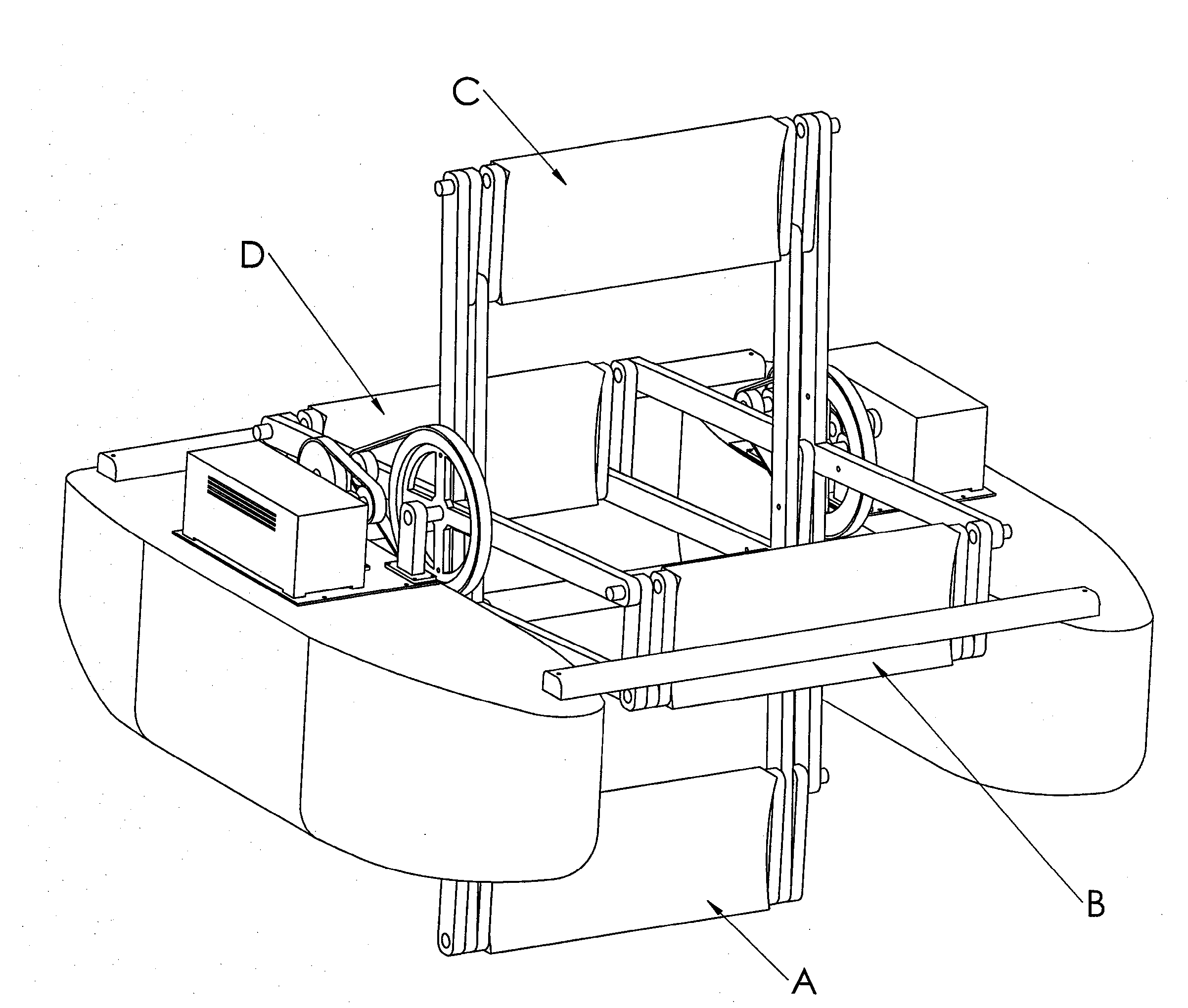
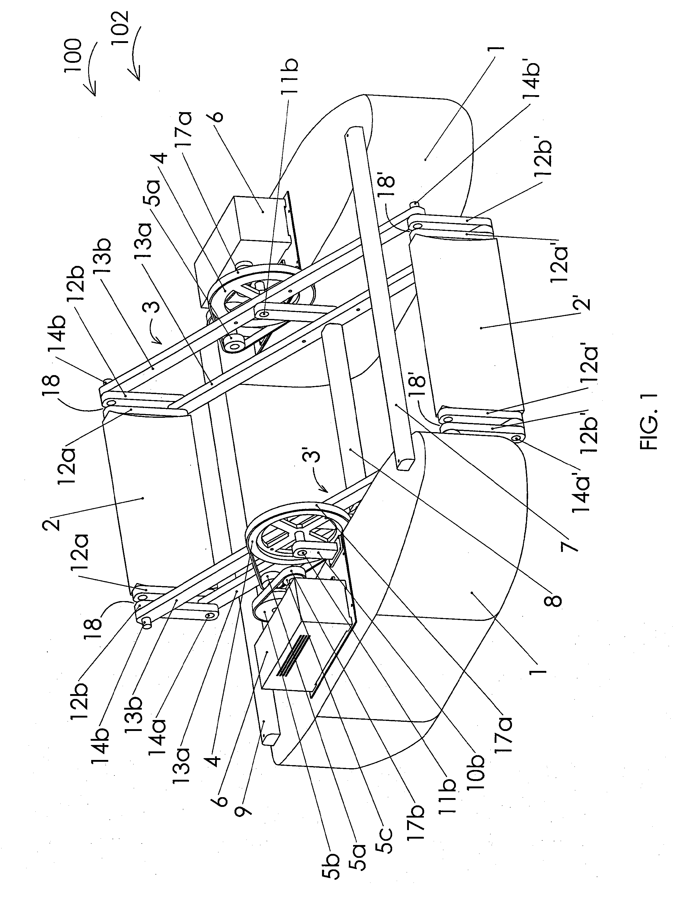
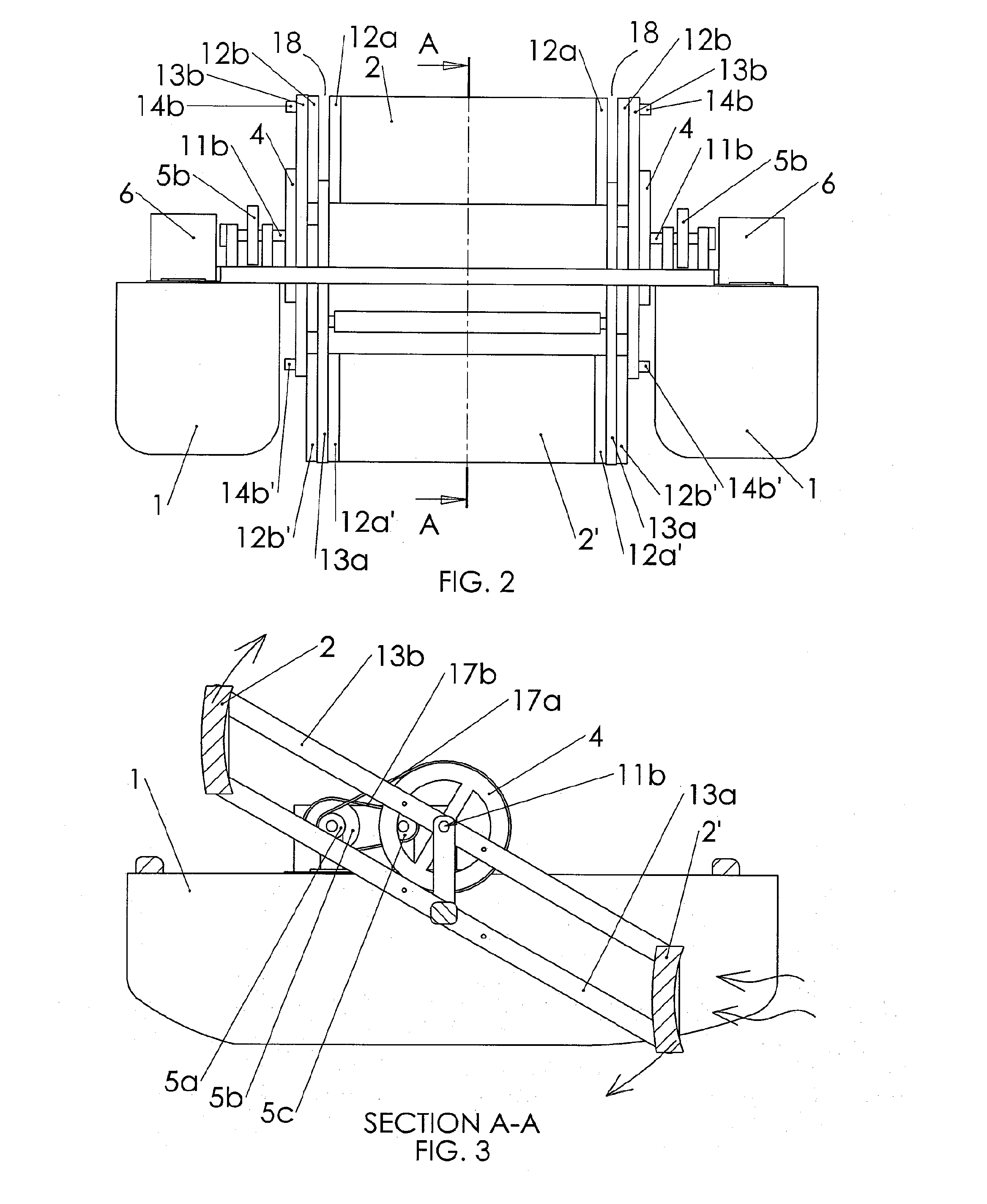
[0027]The present invention relates to a device and method for conversion of kinetic energy, in the form of fluid stream power, into rotational energy by using a novel rotating mechanism which maintains the flow-capturing blades of the device in a constant orientation, substantially perpendicular to the direction of the fluid flow, regardless of the rotation angle of the rotating mechanism. This maximizes the torque generated by the rotation of the rotating mechanism and enables the capture of the fluid's linear momentum in a very efficient way, converting the kinetic energy of the fluid into rotational energy. This rotational energy may then be converted to electricity by means of an electric generator, or it can be used to power a mechanical device, or used for any other desired use.

[0028]The rotating mechanism and flow-capturing blades of the invention form part of a turbine, particularly a drag force turbine, which provides a constant maximal cross-section in front of the fluid ...


PUM


Abstract

The present invention relates to a device and method for capturing the kinetic energy of a fluid and converting it to rotational, electrical or mechanical energy, the device including a rotating bar mechanism for enabling rotation of a flow-capturing blade around a central axis of the device while retaining the flow-capturing blade in an orientation perpendicular to the fluid flow direction throughout the rotation cycle.

Description

FIELD OF THE INVENTION[0001]The present invention relates to power converters in general and, in particular, to a device for conversion of fluid power, such as wind or hydro power.BACKGROUND OF THE INVENTION[0002]There are known in the art devices for converting fluid power into electricity. Typically, these devices include multiple blades that are fixed to a single rotating axle, like a windmill. This single rotating axle is used as the shaft to rotate the rotor of an electric generator. The force of the flow stream causes the blades to turn the single axle and power the generator. As the single axle rotates, the blades change their orientation relative to the direction of the flow.[0003]There are also known devices with a plurality of blades where each blade is mounted for rotation about an axle. These axles are secured to a larger shaft which is used to rotate the rotor of an electric generator. The force generated by a stream of water or wind rotates the blades and turns the sha...

Claims


Application Information

Patent Timeline
Patent Type & Authority Applications(United States)
IPC IPC(8): F03B17/06F03B13/00F03D3/06
CPCF03B17/067F03B13/00F03D3/068F03D3/002F03D3/005F05B2210/16Y02E10/30Y02E10/74Y02E10/20
Inventor HARARI, TZACH
Owner HARARI TZACH
Why Eureka
Try Eureka