Battery device, control method, and electric vehicle

a battery device and control method technology, applied in the direction of electric devices, wheelchairs/patient conveyances, and arrangements for several simultaneous batteries, can solve the problem that the battery device might be easily stolen, and achieve the effect of high-security anti-theft function

Inactive Publication Date: 2014-04-10
SONY CORP
View PDF3 Cites 37 Cited by
  • Summary
  • Abstract
  • Description
  • Claims
  • Application Information

AI Technical Summary

Benefits of technology

[0017]According to one aspect of this technology, it ...

Problems solved by technology

Therefore, only the batter...

Method used


Image

  • Battery device, control method, and electric vehicle
  • Battery device, control method, and electric vehicle
  • Battery device, control method, and electric vehicle

Examples


first embodiment

1. First Embodiment

[Configuration Example of Power-Assisted Bicycle

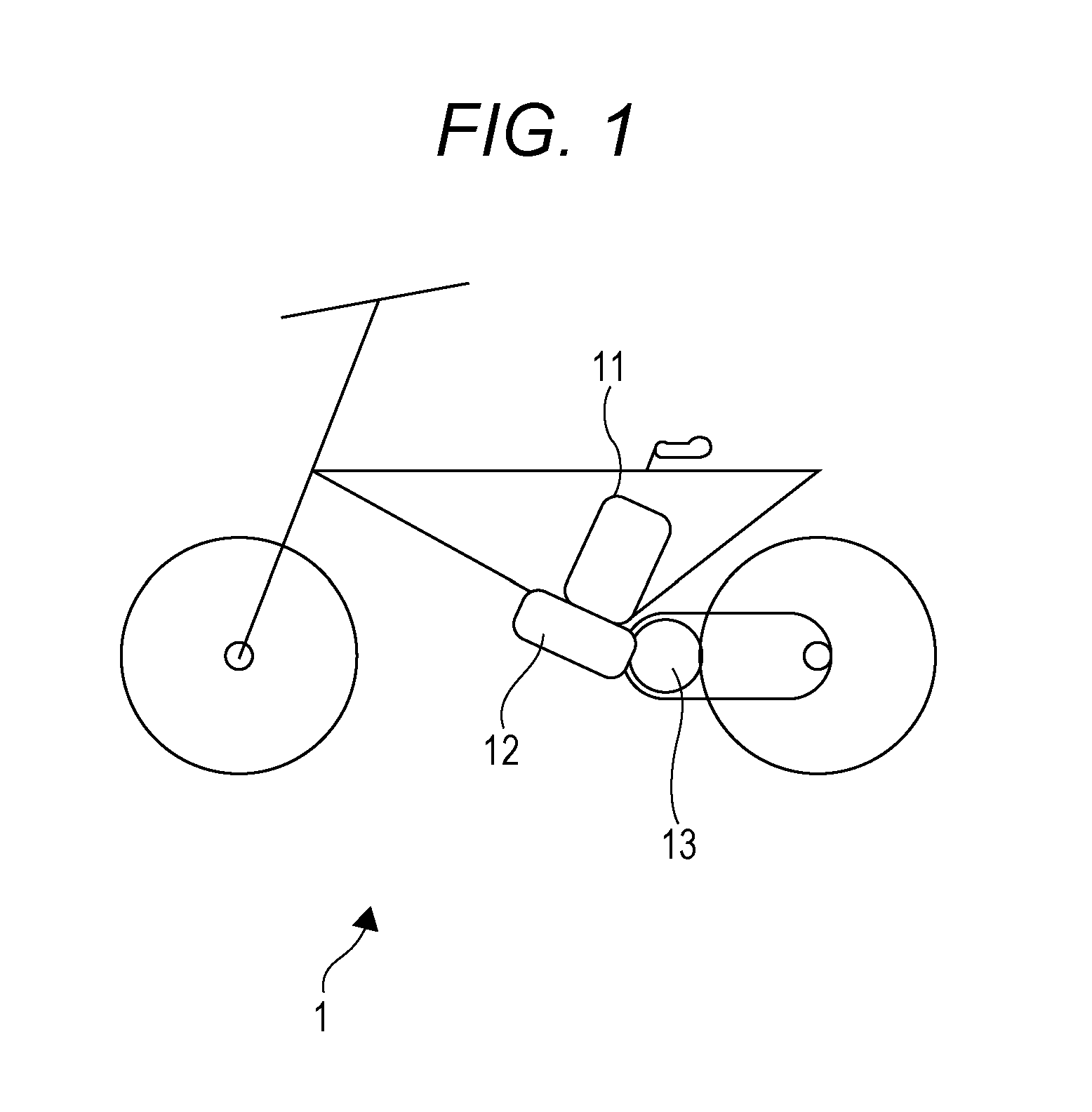
[0026]FIG. 1 is a view illustrating a configuration example of power-assisted bicycle.

[0027]A power-assisted bicycle 1 is a bicycle, which generated auxiliary electric driving force in addition to human driving force to travel forward.

[0028]As illustrated in FIG. 1, a principal framework of the power-assisted bicycle 1 is composed of a body frame made of a metallic pipe to which a front wheel, a rear wheel, a handlebar, a saddle, a pedal and the like are attached. The frame is provided with a frame device 12 for supplying a drive device 13 with power from a battery device 11, and the rear wheel is rotated by tread force applied to the pedal transmitted to the drive device 13 through a control circuit (not illustrated) and the like. As a result, it becomes possible to allow the power-assisted bicycle 1 to travel forward.

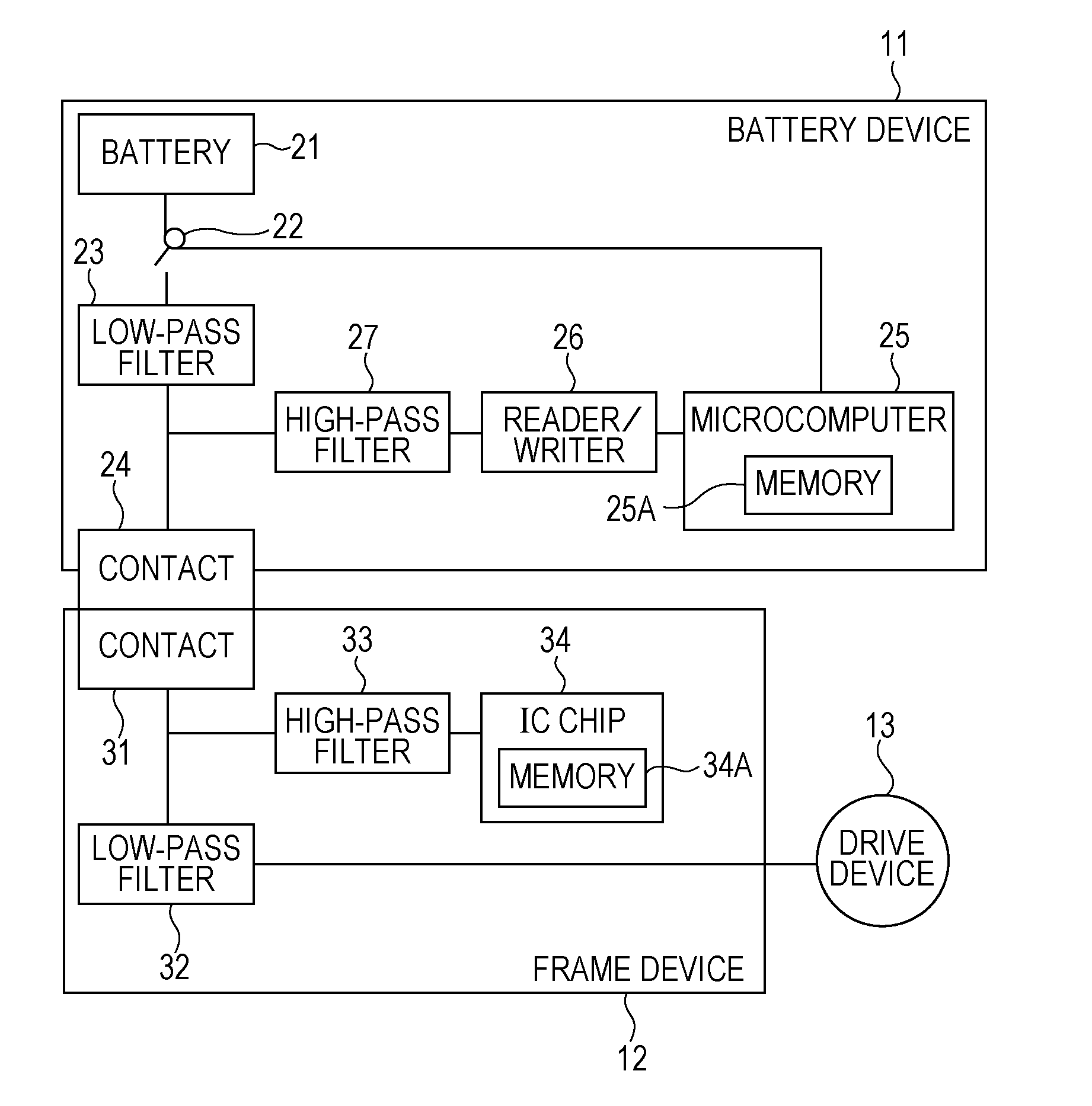
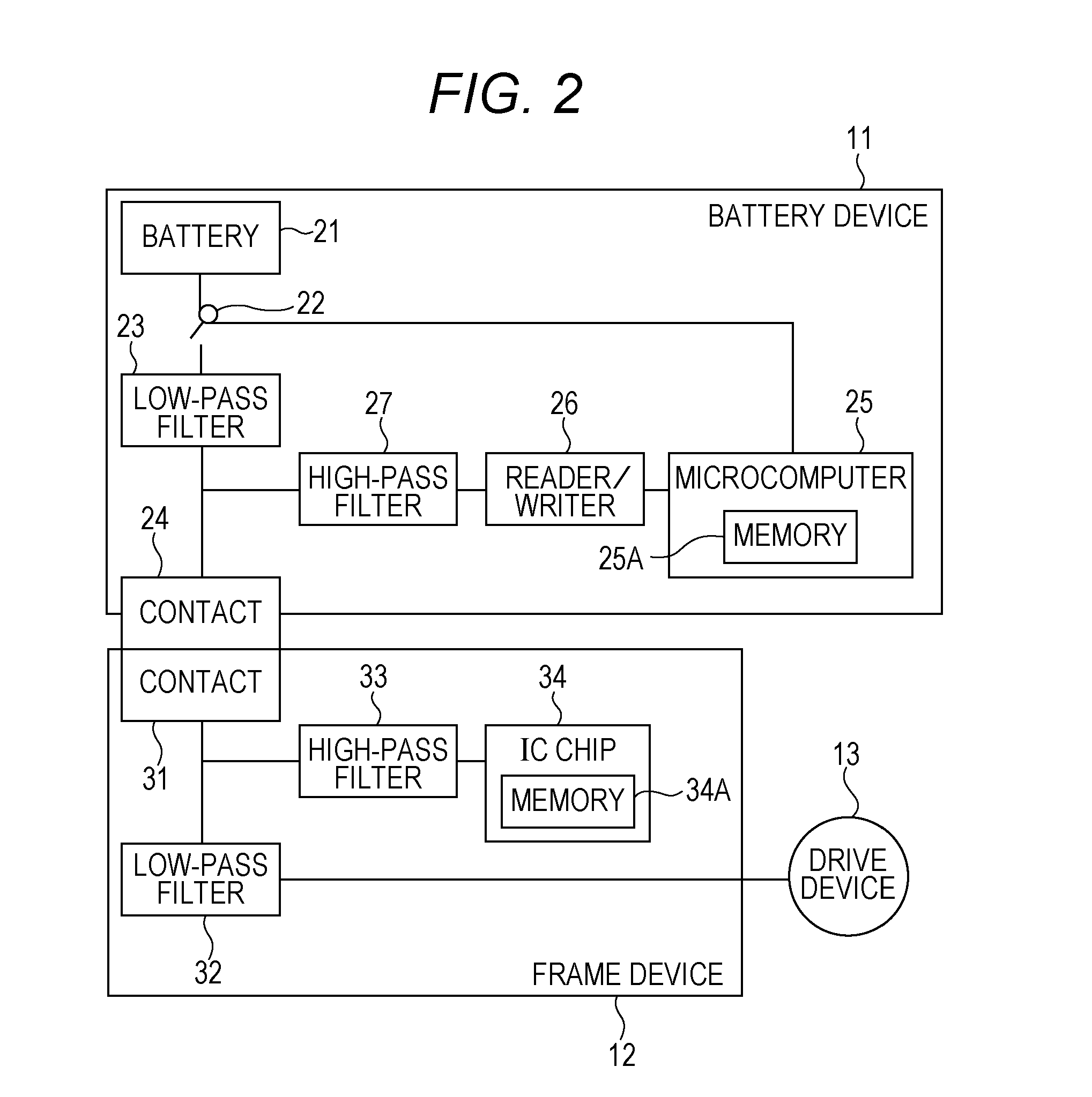
[0029]Meanwhile, the frame device 12 has a shape on which the battery device 11 may be mounted and...

second embodiment

2. Second Embodiment

[0071]It is supposed that a battery device 11 is charged once every one-day to one-week use, for example, as described above, it is required to detach the same from a frame device 12 to charge depending on frequency of use of a power-assisted bicycle 1. A battery charging system for charging the battery device 11 is next described.

[0072][Configuration Example of Battery Charging System]

[0073]As illustrated in FIG. 4, a battery charging system 2 is composed of the battery device 11 and a charging device 14, which charges the battery device 11.

[0074]An AC plug 15 of the charging device 14 is connected to a household outlet 16, so that the charging device 14 may use AC power supply through the AC plug 15. The charging device 14 has a shape on which the battery device 11 may be put and is provided with a power supply terminal (contact 43 in FIG. 5) in a position corresponding to a power supply terminal (contact 24 in FIG. 5) of the battery device 11 to be electricall...


PUM


Abstract

This technology relates to a battery device, a control method, and an electric vehicle capable of providing a highly secure anti-theft function. A battery outputs DC power through a power line, a reader/writer communicates by outputting a high-frequency signal through the power line to read authentication information of an electronic device when the electronic device is connected to the battery through the power line, a microcomputer stores the read authentication information and controls the battery when first connection to the electronic device is performed, and performs an authentication process of the electronic device based on the read authentication information and the authentication information stored in the first connection and controls the battery according to a result of the authentication process of the electronic device when second or subsequent connection to the electronic device is performed. This technology may be applied to the battery device mounted on a power-assisted bicycle, for example.

Description

TECHNICAL FIELD [0001]This technology relates to a battery device, a control method, and an electric vehicle, and especially relates to the battery device, the control method, and the electric vehicle capable of providing a highly secure anti-theft function.BACKGROUND ART[0002]Recently, a power-assisted bicycle becomes widely used (for example, refer to Patent Document 1).[0003]It is supposed that the battery device mounted on the power-assisted bicycle is charged once every one-day to one-week use, so that this is designed to be easily attached / detached to / from a bicycle main body and carried for convenience. Therefore, only the battery device might be easily stolen.CITATION LISTPatent Document [0004]Patent Document 1: JP 2008-260400 ASUMMARY OF THE INVENTIONProblems to be Solved by the Invention [0005]The surest way to prevent the battery device from being stolen is to detach the battery device from the bicycle when getting away from the bicycle; however, it is necessary to carry ...

Claims


Application Information

Patent Timeline
IPC IPC(8): H02J7/00B60R16/033B60L3/00B62H5/00B62M6/90E05B49/00E05B83/00H01M2/10H01M10/44
CPCB60R16/033H02J7/0063H01M10/4257H01M10/44H01M2010/4278H01M2220/20B62M6/90B62H5/00B62H5/20B60L2200/12B60L2200/34B60L2200/46Y02T90/16Y02T90/14Y04S30/14B62M6/45B62M6/75H02J7/0013H04B2203/5416Y02T10/7072B60L53/14B60L53/65H02J7/00045Y02T10/70Y02T90/12Y02T90/167Y02E60/10
Inventor TAKEMURA, KAZUYOSHIWASHIRO, TAKANORISOMA, ISAO
Owner SONY CORP
Why Eureka
Try Eureka