Dual display ct scanner user interface

a ct scanner and user interface technology, applied in the field of ct imaging, can solve the problems of reducing the overall efficiency long bottlenecks, and little thought given to the user interface design of the ct scanner in regard to addressing actual working conditions and customer needs, and achieve the effect of simplifying the user interface for the operator

Active Publication Date: 2014-04-10
GENERAL ELECTRIC CO
View PDF3 Cites 37 Cited by
  • Summary
  • Abstract
  • Description
  • Claims
  • Application Information

AI Technical Summary

Benefits of technology

[0006]Embodiments of the invention are directed to a CT user interface configured to enable multi-tasking workflow, collaboration, multiple throughput use cases, and consistency in scan quality.
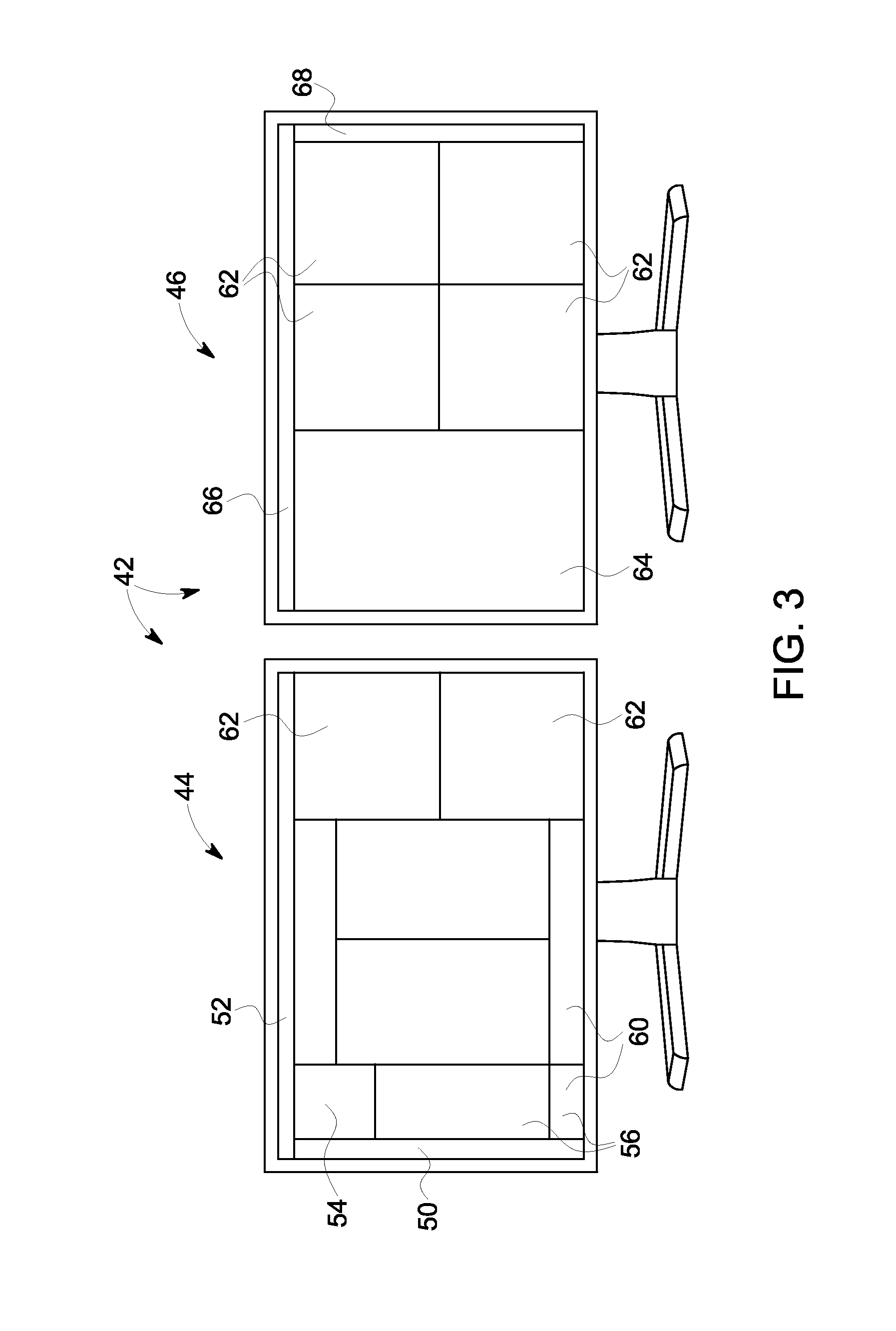
[0007]In accordance with one aspect of the invention, a user interface for a CT imaging system includes a first display configured to enable an operator to perform set-up and scanning tasks associated with performing a CT scan on one or more patients and a second display configured to enable the operator to perform image post-processing tasks associated with the CT scans on the one or more patients, with each of the first display and the second display being configured to selectively display a plurality of distinct display zones thereon that includes a zone on the first display configured to enable the operator to create a record for each of a plurality of patients and an exam set-up and protocol selection zone on the first display configured to enable the operator to select, for a selected patient, a scan protocol for performing a CT scan on the selected patient. The plurality of display zones also includes a task list zone on the first display configured to display all steps and sub-steps of a CT scan to be performed for a selected patient based on the selected scan protocol and a settings zone and a scanning zone on the first display configured to display and enable operator selection of a plurality of scan parameters related to the selected scan protocol for the selected patient, with any general user interface elements not needed for the selected scan protocol for the selected patient not being displayed on the first and second displays, so as to simplify the user interface for the operator.
[0008]In accordance with another aspect of the invention, a user interface for a CT imaging system includes a first display configured to enable an operator to perform set-up and scanning tasks associated with performing a CT scan on one or more patients and a second display configured to enable the operator to perform image post-processing tasks associated with the CT scans on the one or more patients. Each of the first display and the second display are configured to display a plurality of distinct display zones thereon, with the plurality of display zones including a tabs zone on the first display having a plurality of tabs each directed to a distinct subject, with the tabs being selectable by the operator to select a subject. The plurality of display zones also includes a task list zone on the first display that is configured to display all steps and sub-steps in a CT scan for a subject selected via a tab in the tabs zone and enable operator selection of a particular step and sub-step, wherein the steps and sub-steps are selectable by the operator. The plurality of display zones further includes settings and scanning zones that are selectively displayed on the first display for a respective subject whose tab is selected and for a respective sub-step selected in the task list zone, with the settings and scanning zones being configured to display subject specific and scan specific information. Subject specific and scan specific information for subjects whose respective tabs are not currently selected is not displayed on the first and second displays, so as to simplify the user interface for the operator.

Problems solved by technology

It is well recognized that CT scanner technology is growing increasingly complex and capable as innovations in electronics, computing, and imaging physics enable both new clinical applications and bring what were considered boutique and difficult CT examinations into the realm of a routine case.
However, in evolving to keep pace with advances in technology, little thought has been given to CT scanner user interface design with respect to addressing actual working conditions and customer needs.
Accordingly, existing CT scanner UI designs posses a linear, sequential architecture, and become consumed with system tasks, such as post-processing, thereby causing long bottlenecks that reduces the overall efficiency of the CT scanner.
Existing CT scanner UI designs also fail to properly identify the users involved at different points in the patient experience with a CT study and lack a clear presentation and prioritized design framework supporting the fundamental workflow of a patient CT exam, which progresses as: Setup Exam>Customize Preferences>Adjust for Patient>Capture & Evaluate>Create Final Images>Finish.

Method used


Image

  • Dual display ct scanner user interface
  • Dual display ct scanner user interface
  • Dual display ct scanner user interface

Examples


Embodiment Construction

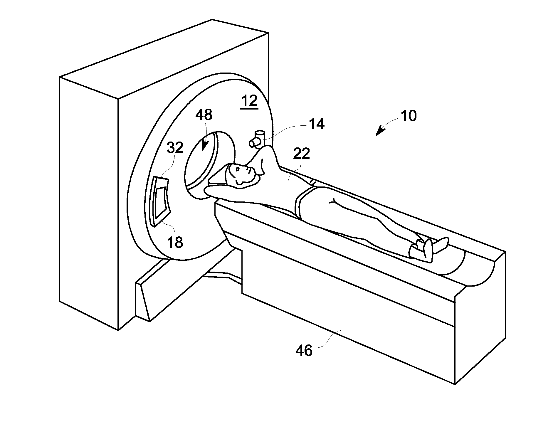
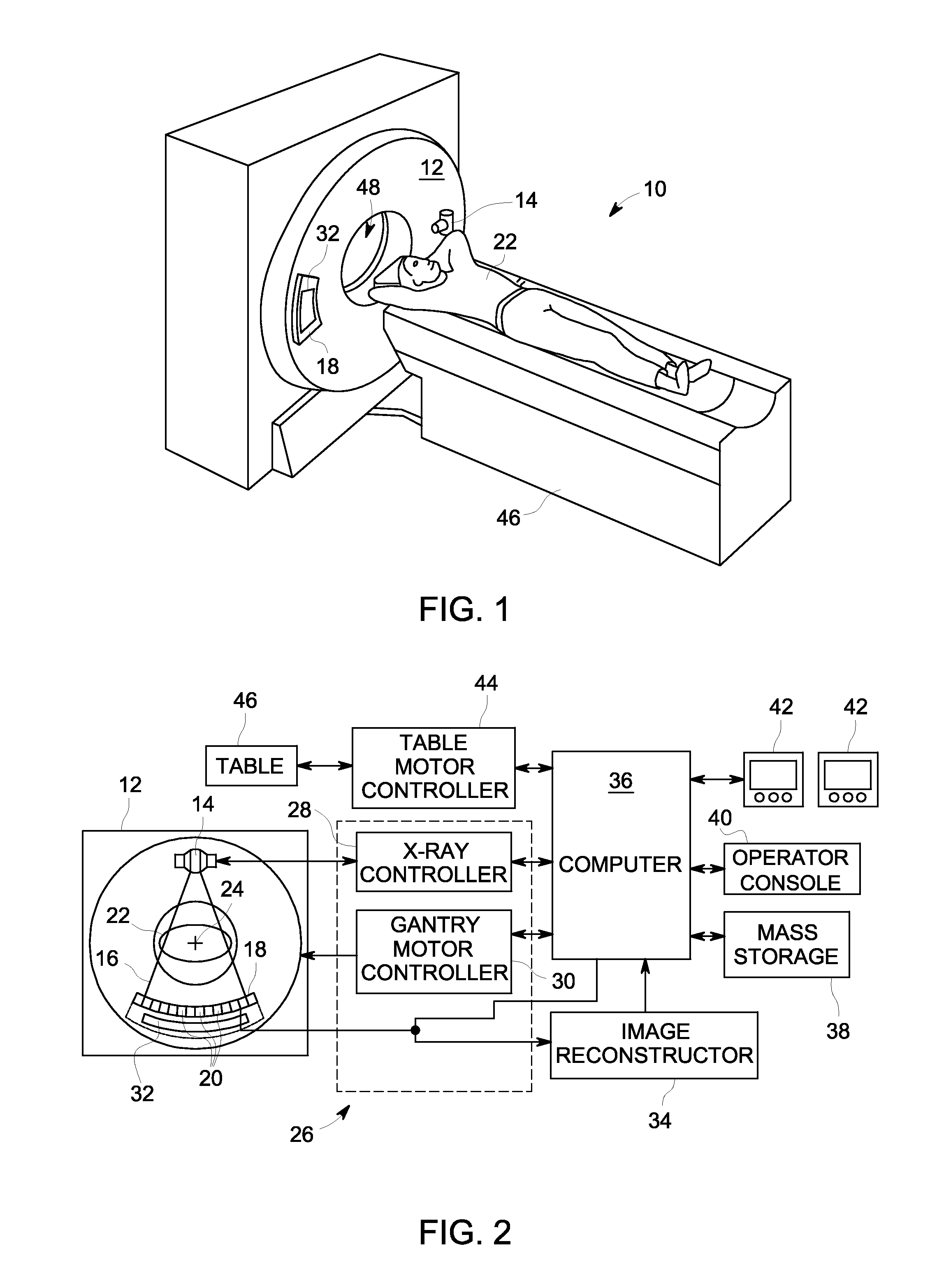
[0032]The operating environment of the invention is described with respect to a sixty-four-slice computed tomography (CT) system. However, it will be appreciated by those skilled in the art that the invention is equally applicable for use with other multi-slice configurations. Moreover, the invention will be described with respect to the detection and conversion of x-rays. However, one skilled in the art will further appreciate that the invention is equally applicable for the detection and conversion of other high frequency electromagnetic energy. The invention will be described with respect to a “third generation” CT scanner, but is equally applicable with other CT systems.

[0033]Referring to FIG. 1, a computed tomography (CT) imaging system 10 is shown as including a gantry 12 representative of a “third generation” CT scanner. Gantry 12 has an x-ray source 14 that projects a beam of x-rays toward a detector assembly or collimator 18 on the opposite side of the gantry 12. Referring ...


PUM


Abstract

A CT user interface includes first and second displays that selectively display distinct display zones thereon. The first display includes a zone enabling the operator to create a record for each of a plurality of patients and an exam set-up and a protocol selection zone enabling the operator to select a scan protocol for performing a CT scan on a selected patient. A task list zone on the first display displays all steps and sub-steps of a CT scan for a selected patient based on the selected scan protocol, and a settings zone and a scanning zone on the first display displays and enables operator selection of a plurality of scan parameters related to the selected scan protocol. Any general user interface elements not needed for the selected scan protocol are not displayed on the first and second displays, so as to simplify the user interface for the operator.

Description

BACKGROUND OF THE INVENTION[0001]Embodiments of the invention relate generally to computed tomography (CT) imaging and, more particularly, to a CT user interface configured to enable multi-tasking workflow, collaboration, multiple throughput use cases, and consistency in scan quality.[0002]Typically, in computed tomography (CT) imaging systems, an x-ray source emits a fan-shaped beam toward a subject or object, such as a patient or a piece of luggage. The beam, after being attenuated by the subject, impinges upon an array of radiation detectors. The intensity of the attenuated beam radiation received at the detector array is typically dependent upon the attenuation of the x-ray beam by the subject. Each detector element of the detector array produces a separate electrical signal indicative of the attenuated beam received by each detector element. The electrical signals are transmitted to a data processing system for analysis which ultimately produces an image.[0003]Generally, the x-...

Claims


Application Information

Patent Timeline
Patent Type & Authority Applications(United States)
IPC IPC(8): G06K9/00A61B6/03
CPCA61B6/032A61B6/463A61B6/464A61B6/465A61B6/468A61B6/469A61B6/481A61B6/488A61B6/504A61B6/54A61B6/541G16H40/63G16Z99/00
Inventor PROFIO, MARK VINCENTMCDANIEL, HOLLY ANNJONES, CHERYL RUTHPATZ, TABB ALANWIMMER, MEGAN ELIZABETHFOX, AMANDA JEANWETTERSTEN, JON V.KING, SIMON J.JONSSON, STINA MARIA
Owner GENERAL ELECTRIC CO
Why Eureka
Try Eureka