Robot cleaner and control method thereof

a robot cleaner and robot technology, applied in the field of robot cleaners, can solve the problems of long time for direction change, large amount of dust spilled by robot cleaners at direction change points, and large amount of collected dust, so as to reduce the number of stops, improve cleaning efficiency, and reduce the time consumed for cleaning

Active Publication Date: 2014-04-10
SAMSUNG ELECTRONICS CO LTD
View PDF3 Cites 35 Cited by
  • Summary
  • Abstract
  • Description
  • Claims
  • Application Information

AI Technical Summary

Benefits of technology

[0046]Therefore, since the robot cleaner may perform cleaning without scattering dust, the efficiency of cleaning may be improved. Particularly, in the case of wet cleaning, the robot cleaner may perform cleaning while driving dust without scattering the dust.
[0047]Also, by reducing the number of stops when the traveling direction of the robot cleaner changes during cleaning, it may be possible to reduce the time consumed for cleaning, thereby possibly improving an initial coverage rate, possibly resulting in improvement of user satisfaction.
[0048]In addition, by removing dust remaining between the blade and the main brush, it may be possible to prevent the elements of the robot cleaner from being damaged.

Problems solved by technology

Also, the zig-zag pattern requires two stops and two rotations to change the travel direction, and needs a long time for direction change since an acceleration / deceleration velocity profile is applied for stops and rotations.
Furthermore, upon stops and rotations for direction change during cleaning based on the zig-zag pattern, the robot cleaner tends to spill collected dust.
Particularly, in the case of wet cleaning, the robot cleaner may spill a large quantity of dust at direction-change points since it wipes off dust with a rag instead of sucking dust up.
In addition, the robot cleaner has a problem that dust is gathered between a main brush and a blade made of a soft material, the blade installed in a reverse-inclined direction in the back of the brush.
Particularly, a blade made with the soft material often tilts back when the robot cleaner moves, which widens the distance from the main brush.

Method used


Image

  • Robot cleaner and control method thereof
  • Robot cleaner and control method thereof
  • Robot cleaner and control method thereof

Examples


Embodiment Construction

[0065]Reference will now be made in detail to one or more embodiments, illustrated in the accompanying drawings, wherein like reference numerals refer to like elements throughout. In this regard, embodiments of the present invention may be embodied in many different forms and should not be construed as being limited to embodiments set forth herein, as various changes, modifications, and equivalents of the systems, apparatuses and / or methods described herein will be understood to be included in the invention by those of ordinary skill in the art after embodiments discussed herein are understood. Accordingly, embodiments are merely described below, by referring to the figures, to explain aspects of the present invention.

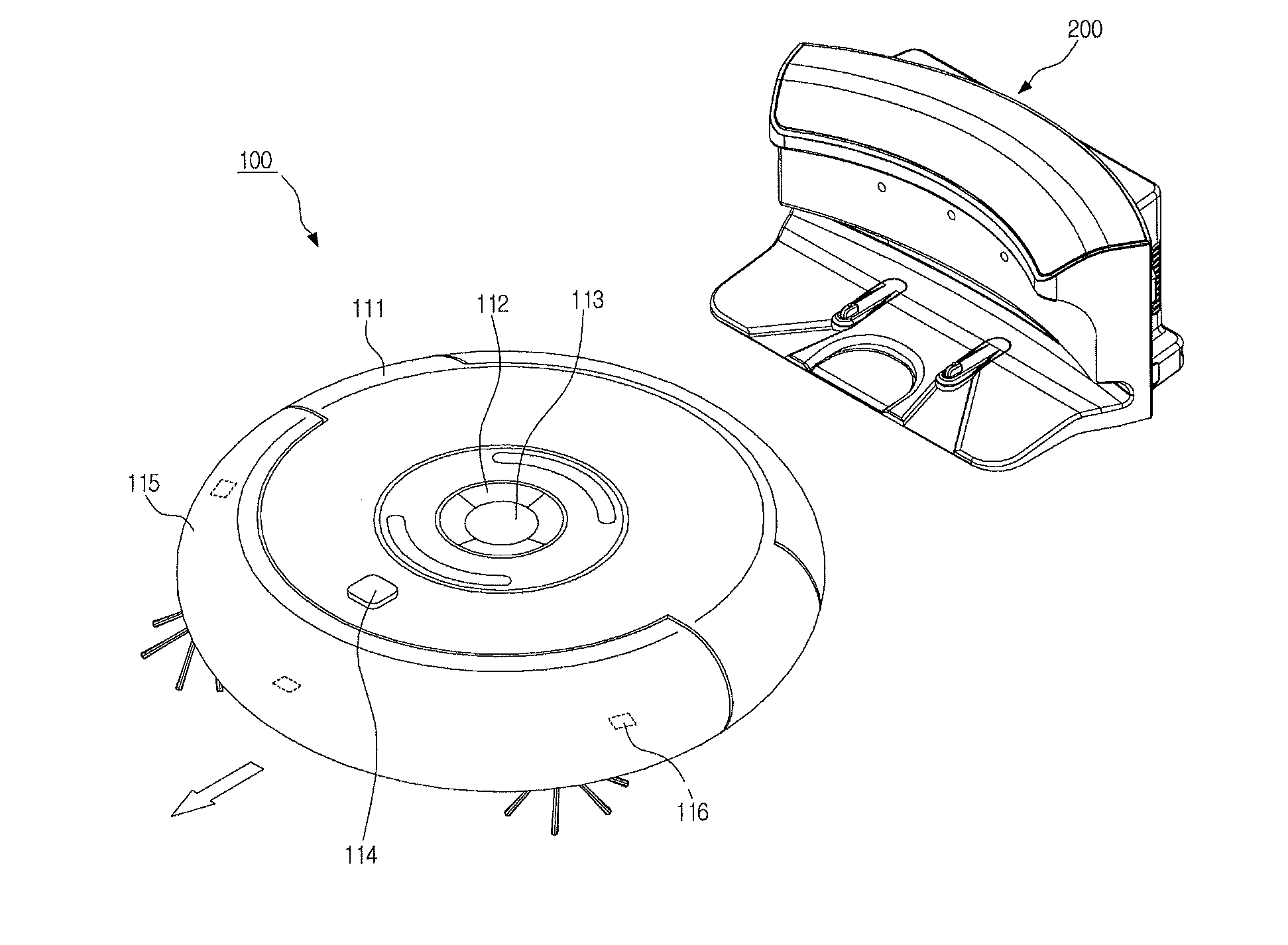
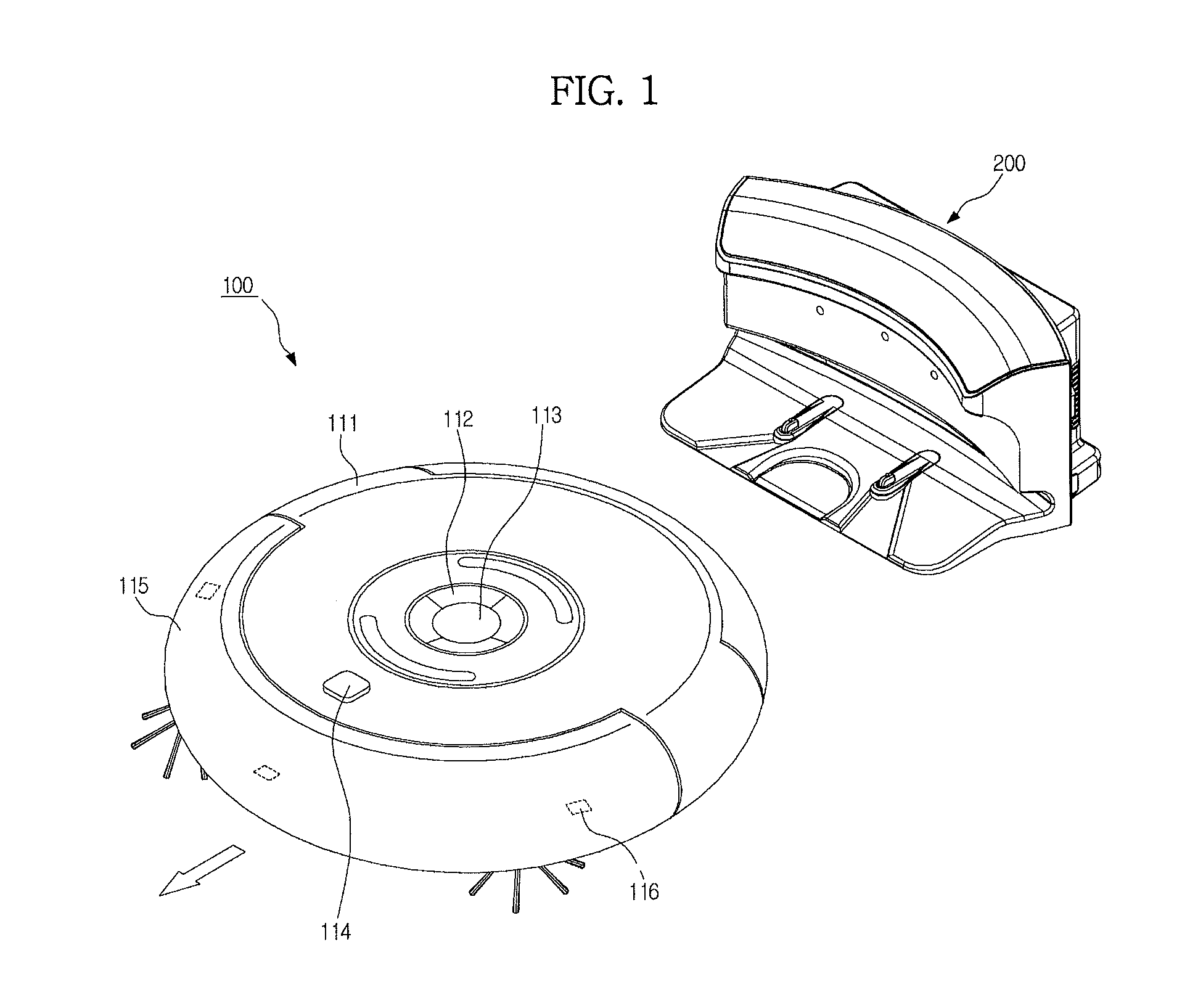
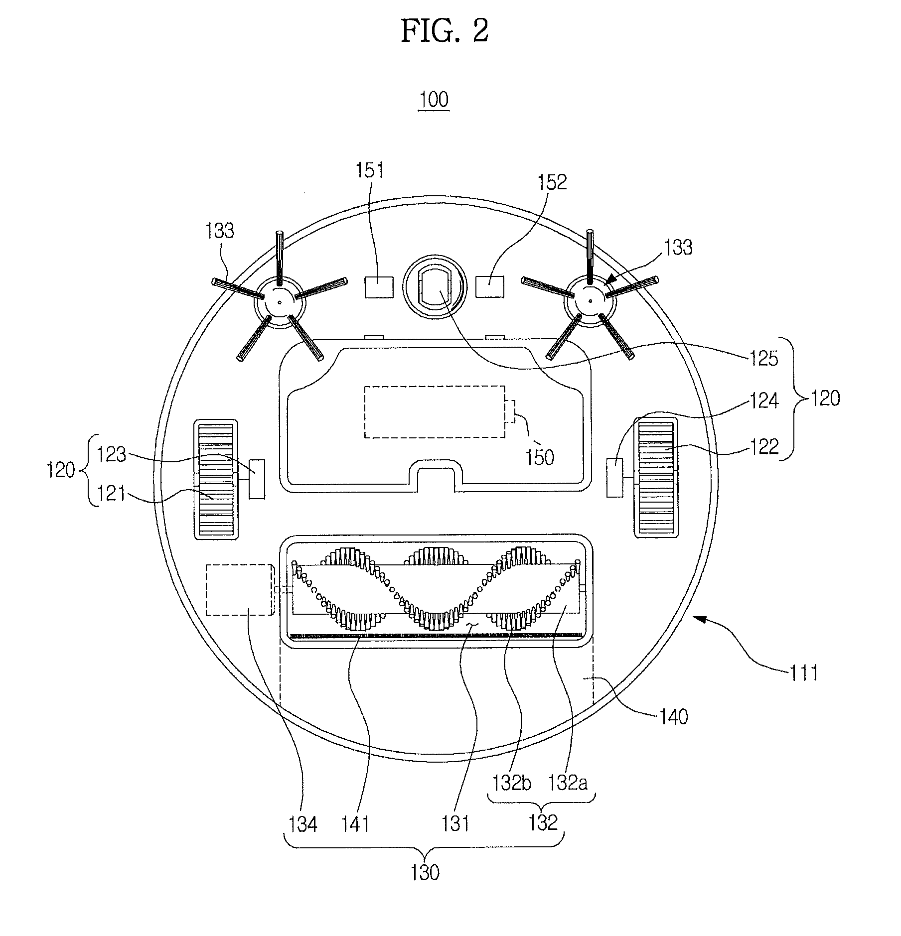
[0066]FIGS. 1 through 3 illustrate a robot cleaner 100 according to one or more embodiments. In detail, FIG. 1 is a top perspective view of a robot cleaner 100, and FIGS. 2 and 3 are bottom perspective views of a robot cleaner 100, wherein FIG. 2 shows an example and F...


PUM


Abstract

A control method of a robot cleaner for traveling to clean includes checking information about a predetermined traveling pattern; determining a traveling trajectory based on a traveling speed; generating a traveling pattern based on the determined traveling trajectory and the information about the predetermined traveling pattern, wherein the traveling pattern includes a first straight path, a first rotation path connected to the first straight path and for rotation in a first direction, a second straight path connected to the first rotation path, and a second rotation path connected to the second straight path and for rotation in a second direction; and repeatedly traveling along the generated traveling pattern at regular intervals. Therefore, since the robot cleaner performs cleaning without scattering dust, the efficiency of cleaning may be improved.

Description

CROSS-REFERENCE TO RELATED APPLICATIONS[0001]This application claims the benefit of Korean Patent Application No. 10-2012-0111869, filed on Oct. 9, 2012 in the Korean Intellectual Property Office, the disclosure of which is incorporated herein by reference.BACKGROUND[0002]1. Field[0003]One or more embodiments relate to a robot cleaner for creating a pattern capable of enhancing the efficiency of cleaning, and a control method thereof.[0004]2. Description of the Related Art[0005]In general, a robot cleaner automatically cleans an area to be cleaned by sucking up foreign substances such as dust from a floor while autonomously traveling about the cleaning area without user manipulation.[0006]During cleaning, the robot cleaner determines a distance to an obstacle, e.g., furniture, office appliances, walls, etc., present in the cleaning area using a sensor, and travels about the cleaning area without collision with the obstacle based on the determined distance.[0007]Cleaning a given clea...

Claims


Application Information

Patent Timeline
Patent Type & Authority Applications(United States)
IPC IPC(8): A47L11/40B25J9/00
CPCA47L11/4011B25J9/0003A47L11/4061G05D1/0219G05D2201/0215A47L2201/04A47L9/28G05D1/02B25J13/08B25J9/16
Inventor KIM, SHINSONGLEE, JU SANGHONG, JUN PYO
Owner SAMSUNG ELECTRONICS CO LTD
Why Eureka
Try Eureka