Attitude Reference for Tieback/Overlap Processing

a technology of attitude reference and processing method, which is applied in the direction of survey, directional drilling, borehole/well accessories, etc., can solve the problems of skewing measurement accuracy, reducing the overall survey accuracy of the gyrocompass mwd system, and many factors combining to influence the trajectory of the drilled borehol

Active Publication Date: 2014-04-17
SCIENCE DRILLING INTERNATIONAL INC
View PDF3 Cites 19 Cited by
  • Summary
  • Abstract
  • Description
  • Claims
  • Application Information

AI Technical Summary

Benefits of technology

[0005]The present disclosure provides for a method for computing the orientation of a MWD system in a borehole. The method may include providing a MWD system, the MWD system including multiple sensors, the data collected by the sensors interpreted by sensor models having adjustable sensor model parameters, the MWD system having an orientation, the orientation including azimuth and inclination. The method may further includes positioning the MWD system on a drill string. The method may further include positioning the drill string at a depth within a borehole drilled from a surface location, the depth measured from the location of the MWD system to the surface location, the direction of the borehole generally being represented by the orientation of the MWD system; moving, by a motion of the drill string, the location of the MWD system within the borehole from a first depth to a second depth; sensing changes in the orientation of the MWD system using one or more sensors of the multiple sensors as the MWD system is moved from the first depth to the second depth; and calculating the change in orientation of the MWD system between the first and second depths.
[0006]The present disclosure also provides for a method for computing the orientation of a MWD system in a borehole. The method may include providing a MWD system, the MWD system including multiple sensors, the data collected by the sensors interpreted by sensor models having adjustable sensor model parameters, the MWD system having an orientation, the orientation including azimuth and inclination. The method may further include positioning the MWD system on a drill string. The method may further include positioning the drill string at an upper depth within a borehole drilled from a surface location into an earthen formation, the depth measured from the location of the MWD system to the surface location, the direction of the borehole in which the MWD system generally being represented by the orientation of the MWD system; taking a compass shot using two or more sensors of the multiple sensors at the upper depth to determine the orientation of the MWD system at the upper depth; drilling deeper into the earthen formation, the MWD system thus moved to a lower depth; moving, by a motion of the drill string, the MWD system within the borehole either from the upper depth to the lower depth or from the lower depth to the upper depth; sensing changes in the orientation of the MWD system using one or more sensors of the multiple sensors as the MWD system is moved; calculating the change in orientation of the MWD system between the upper and lower depths; and computing the orientation of the MWD system at the lower depth using the calculated change in orientation between the upper and lower depths and the orientation of the MWD system at the upper depth.

Problems solved by technology

Many factors may combine to unpredictably influence the trajectory of a drilled borehole.
Error accumulated between multiple survey stations caused by, for example, the presence of physical factors or anomalies may skew measurement accuracy.
For example, MWD systems which rely on magnetometers may be influenced by magnetic interference both on and off the drill string.
Additionally, gyrocompasses naturally tend to lose accuracy at higher inclinations which may reduce overall survey accuracy in gyrocompass MWD systems.

Method used


Image

  • Attitude Reference for Tieback/Overlap Processing
  • Attitude Reference for Tieback/Overlap Processing
  • Attitude Reference for Tieback/Overlap Processing

Examples


Embodiment Construction

[0014]It is to be understood that the following disclosure provides many different embodiments, or examples, for implementing different features of various embodiments. Specific examples of components and arrangements are described below to simplify the present disclosure. These are, of course, merely examples and are not intended to be limiting. In addition, the present disclosure may repeat reference numerals and / or letters in the various examples. This repetition is for the purpose of simplicity and clarity and does not in itself dictate a relationship between the various embodiments and / or configurations discussed.

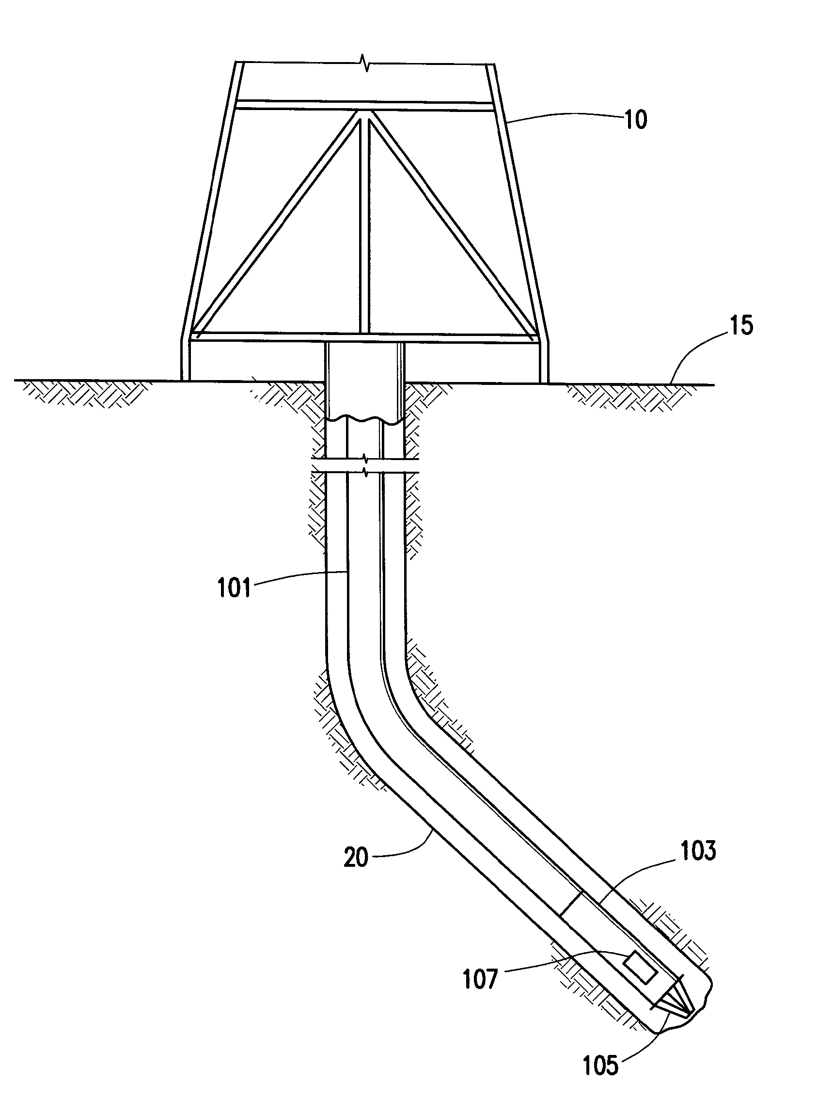
[0015]FIG. 1 depicts the drilling of a deviated borehole with a drill string carrying a measurement while drilling (MWD) system. More particularly, drilling rig 10 at surface 15 is shown drilling borehole 20. Drill string 101 is made up of numerous sections of pipe and includes bottom hole assembly 103 and drill bit 105. As understood in the art, the sections of pipe a...


PUM


Abstract

A method for calculating orientation changes within a borehole using a gyro sensor to detect angular deflection rates in an attitude reference interval as a MWD system is moved from a first to a second location within the borehole. A compass shot may be taken at one or more of the first and second locations using a magnetometer and accelerometer or gyro sensor and accelerometer. Tieback and/or overlap processing may be applied to increase the accuracy of measured orientation within the borehole. Additionally, tieback and/or overlap processing may be applied to adjust sensor model parameters in response to discrepancies between calculated and measured locations. Iterated calculations of orientation change between subsequent intervals may allow MWD orientation to be computed for an entire drilling operation using only a single compass shot.

Description

CROSS-REFERENCE TO RELATED APPLICATIONS[0001]This application is a non-provisional application which claims priority from U.S. provisional application No. 61 / 713,164, filed Oct. 12, 2012.TECHNICAL FIELD / FIELD OF THE DISCLOSURE[0002]The present disclosure relates to surveys in a measurement while drilling (MWD) system, and more particularly to processing methods for data collected by MWD sensors.BACKGROUND OF THE DISCLOSURE[0003]Accurately and precisely determining the position and orientation of a drilling assembly during drilling operations is desirable, particularly when drilling deviated wells. Traditionally, a combination of sensors is used to measure downhole trajectory and subterranean conditions. Data collected in this fashion is usually transmitted to the surface via MWD-telemetry known in the art so as to communicate this trajectory information to the surface. Many factors may combine to unpredictably influence the trajectory of a drilled borehole. Accurate determination of...

Claims


Application Information

Patent Timeline
Patent Type & Authority Applications(United States)
IPC IPC(8): E21B44/00E21B7/04
CPCE21B7/04E21B44/00E21B47/024E21B47/0228G01C5/00G01V3/081G01V9/00
Inventor VANSTEENWYK, BRETT
Owner SCIENCE DRILLING INTERNATIONAL INC
Why Eureka
Try Eureka