X-ray generating apparatus

a generation apparatus and generating technology, applied in the direction of x-ray tube target materials, x-ray tube bonding/fixing, electric discharge tubes, etc., can solve the problems of difficult configuration of compact apparatus, inability to finely control the focus position of the x-ray generating apparatus, and inability to configure the compact apparatus

Active Publication Date: 2014-04-17
RIGAKU CORP
View PDF1 Cites 29 Cited by
  • Summary
  • Abstract
  • Description
  • Claims
  • Application Information

AI Technical Summary

Benefits of technology

[0023]According to the present invention, through the use of the compact and lightweight configuration of the apparatus, the focus position of the electron beam can be finely adjusted.

Problems solved by technology

As described above, since the electromagnetic lens that focuses the electron beam accounts for a large volume, it is hard to configure the compact apparatus.
However, there are demands for the X-ray generating apparatus having a compact and lightweight configuration.
However, even if the electron beam is focused using the permanent magnet, the focus position cannot be finely controlled because of a fixed intensity of the magnetic field.
When the electron beam is focused using the permanent magnet, because of electro-radiative fluctuation due to dimension change of a cathode by aging change and thermal expansion, fluctuation of a magnetic force of a permanent magnet due to heat change, movement of the focus position due to fluctuation of a voltage, displacement of focus position due to temperature rise of a target and dimension change of an X-ray tube and the like, only the permanent magnet cannot always stably generate X-rays.

Method used


Image

  • X-ray generating apparatus
  • X-ray generating apparatus
  • X-ray generating apparatus

Examples


first embodiment

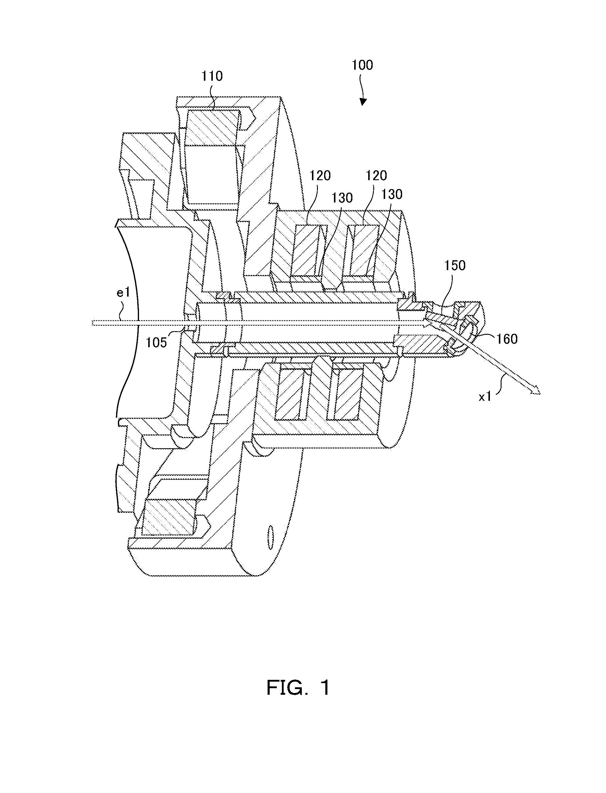
[0037]FIG. 1 is a perspective cross-sectional view illustrating an X-ray generating apparatus 100. The X-ray generating apparatus 100 includes an alignment coil 110, a permanent magnet lens 120, a correction coil 130, a target 150, and an X-ray extraction window 160. The X-ray generating apparatus 100 applies a high voltage of few dozens kilovolt with a cathode serving as a negative electrode and the target 150 serving as a positive electrode and thus causes the electron beam generated by the cathode to collide with the target 150, to thereby generate X rays. Meanwhile, FIG. 1 illustrates a configuration for controlling the focusing of the electron beam, but does not illustrate a peripheral portion of the cathode.

[0038]Generally, the cathode is heated by electric conduction, to emit thermoelectrons. While the traveling direction of the emitted electron beam is controlled by a control voltage applied to the Wehnelt, the emitted electron beam is accelerated by a high voltage applied b...

first example

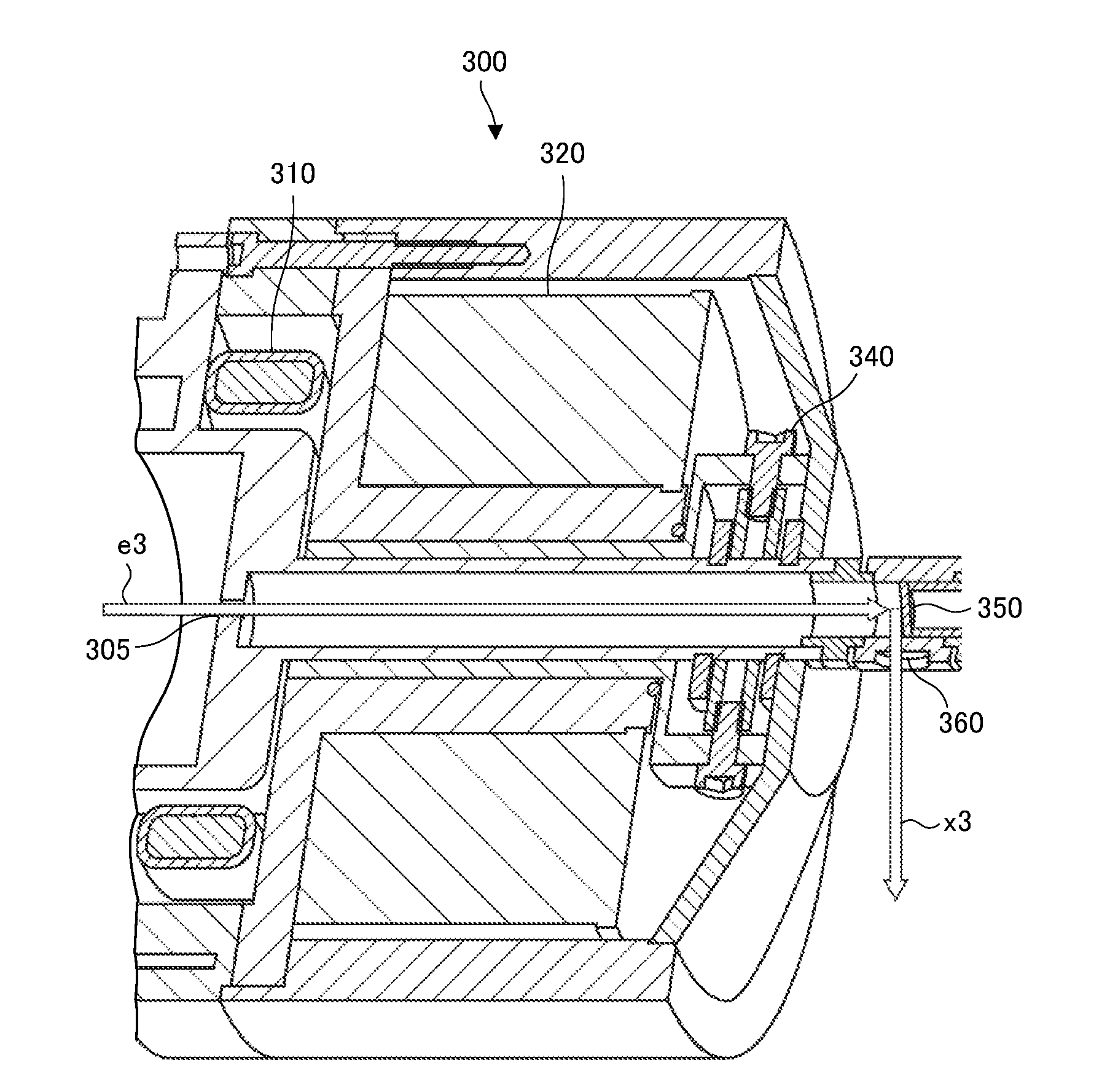
[0052]It has been verified whether the X-ray generating apparatus 100 can generate X-rays with a sufficient small focus size and a sufficient high X-ray intensity through the use of the above-described X-ray generating apparatus 100 and the conventional X-ray generating apparatus 300.

[0053]Both of the apparatuses have been verified under conditions of a load on the target of 45 kV, 0.5 mA, in other words, 22.5 W, and the same temperature and atmospheric pressure. In addition, the same X-ray detector has been used for both of the apparatuses. Furthermore, the same distance condition has been used. In this manner, the generated X-ray spot has been detected. At this time, by the correction coil, the focus position has been adjusted in the traveling direction of the electron beam.

[0054]FIG. 3 is a diagram illustrating an X-ray spot when the correction coil is not sufficiently operated. FIG. 3 illustrates an example of the X-ray spot when currents of two alignment coils are each set to b...

second embodiment

[0058]According to the above-described embodiment, a target 250 is formed of a metal bulk, and may also be a thin metal film formed on the diamond. FIG. 8 is a cross-sectional view illustrating the target 250, which is the thin metal film formed on the diamond. The target 250 is hermetically jointed with a circular-plate-shape diamond plate 256 so as to cover an upper opening portion of a holder portion 251 formed of conductive material and formed into a cylindrical shape, and there is provided a target thin film 255 formed of the conductive material on a surface of the diamond plate 256. The target thin film 255 is provided extending to a side surface of the holder portion 251, and electrically connected to the holder portion 251.

[0059]An open end of the holder portion 251 is formed with a level difference having an inner diameter slightly larger than that of an inner peripheral surface of a cylinder, and the level difference has almost the same height as a thickness of the diamond...


PUM


Abstract

The X-ray generating apparatus 100 applies an electron beam e1 onto a target 150 to generate X-rays x1, and includes a permanent magnet lens 120 configured to focus the electron beam e1, a correction coil 130 provided on a side of the electron beam e1 with respect to the permanent magnet lens 120 and configured to correct a focus position formed by the permanent magnet lens 120 in a traveling direction of the electron beam e1, and a target 150 onto which the focused electron beam is applied. Accordingly, the apparatus configuration can be extremely compact and lightweight in comparison with general apparatuses. Furthermore, by the correction coil 130, the intensity of the magnetic field can be finely adjusted and the focus position in the traveling direction of the electron beam e1 can be finely adjusted.

Description

BACKGROUND OF THE INVENTION[0001]1. Field of the Invention[0002]The present invention relates to an X-ray generating apparatus that applies an electron beam onto a target to generate X-rays.[0003]2. Description of the Related Art[0004]So far, as an X-ray generation source that generates X-rays with a reduced-focus size, a micro-focus X-ray generating apparatus has been widely used. A general X-ray generating apparatus accelerates thermoelectrons emitted from a heated cathode and causes them to collide with a target to emit X-rays. Since an electron current toward the target spreads, application of an appropriate electric field to Wehnelt suppresses spread of the electron current, to thereby cause the electron current to be focused on the target. Since the electron beam minutely reduced in size needs to be applied onto the target, there is known the micro-focus X-ray generating apparatus that controls focusing of the electron beam by using various means.[0005]For example, the X-ray g...

Claims


Application Information

Patent Timeline
Patent Type & Authority Applications(United States)
IPC IPC(8): H01J35/14
CPCH01J35/14H01J2235/081H01J2235/083H01J35/147H01J35/08H01J35/12H01J35/112
Inventor HORVARTH, MARTINMARSIK, JIRIPINA, LADISLAVJELINEK, VACLAVOSAKA, NAOHISAOMOTE, KAZUHIKOKAMBE, MAKOTOJIANG, LICAIKIM, BONGLEA
Owner RIGAKU CORP
Why Eureka
Try Eureka