Component having a micromechanical microphone structure

a micromechanical and microphone technology, applied in the direction of transducer details, electrostatic transducer microphones, electrical transducers, etc., to achieve the highest possible change of capacitance, and increase in microphone sensitivity

Active Publication Date: 2014-04-17
ROBERT BOSCH GMBH
View PDF8 Cites 22 Cited by
  • Summary
  • Abstract
  • Description
  • Claims
  • Application Information

AI Technical Summary

Benefits of technology

[0013]In one especially advantageous specific embodiment of the present invention, the microphone structure includes two acoustically penetrable counter-elements that are formed above and below the diaphragm structure, so that the diaphragm structure is disposed and deflectable in a gap between the two counter-elements. The diaphragm structure is provided on both sides with structural elements oriented perpendicularly to the layer planes, so that they extend to a greater or lesser extent into correspondingly formed and positioned through holes in the counter-elements, depending on the degree of excursion of the diaphragm structure. This microphone structure, toothed on two sides, likewise contributes to the increase in microphone sensitivity, and in addition, permits a differential signal acquisition.
[0014]Moreover, the microphone sensitivity may be increased by the type of connection of the diaphragm structure to the layer construction of the component. The aim is always for an especially great and most plane-parallel excursion possible of the middle area of the diaphragm structure, where the structural elements are formed projecting essentially perpendicularly from the diaphragm plane. In this manner, not only is the highest possible change in capacitance attained, but also the structural elements of the diaphragm structure are prevented from sticking mechanically in the through holes of the counter-element. In this connection, it proves to be advantageous if the diaphragm structure is tied into the layer construction of the component via a spring suspension. Upon exposure to sound, first and foremost, the spring suspension of the diaphragm structure is deformed, while the middle area is deflected in essentially plane-parallel fashion. Alternatively or additionally, the middle area of the diaphragm structure may be stiffened in order to prevent a deformation of the middle area. In this manner, the orientation of the structural elements in alignment with the through holes in the counter-element is also stabilized.
[0015]To reduce the weight of the diaphragm structure, it may be perforated in the middle area, for example, which likewise contributes to the microphone performance of the component according to the present invention.

Problems solved by technology

In addition, in this case, the structural element is deflected in a direction essentially perpendicular to the diaphragm plane, so that it cannot catch an edge in the through hole in the counter-element.

Method used


Image

  • Component having a micromechanical microphone structure
  • Component having a micromechanical microphone structure
  • Component having a micromechanical microphone structure

Examples


Embodiment Construction

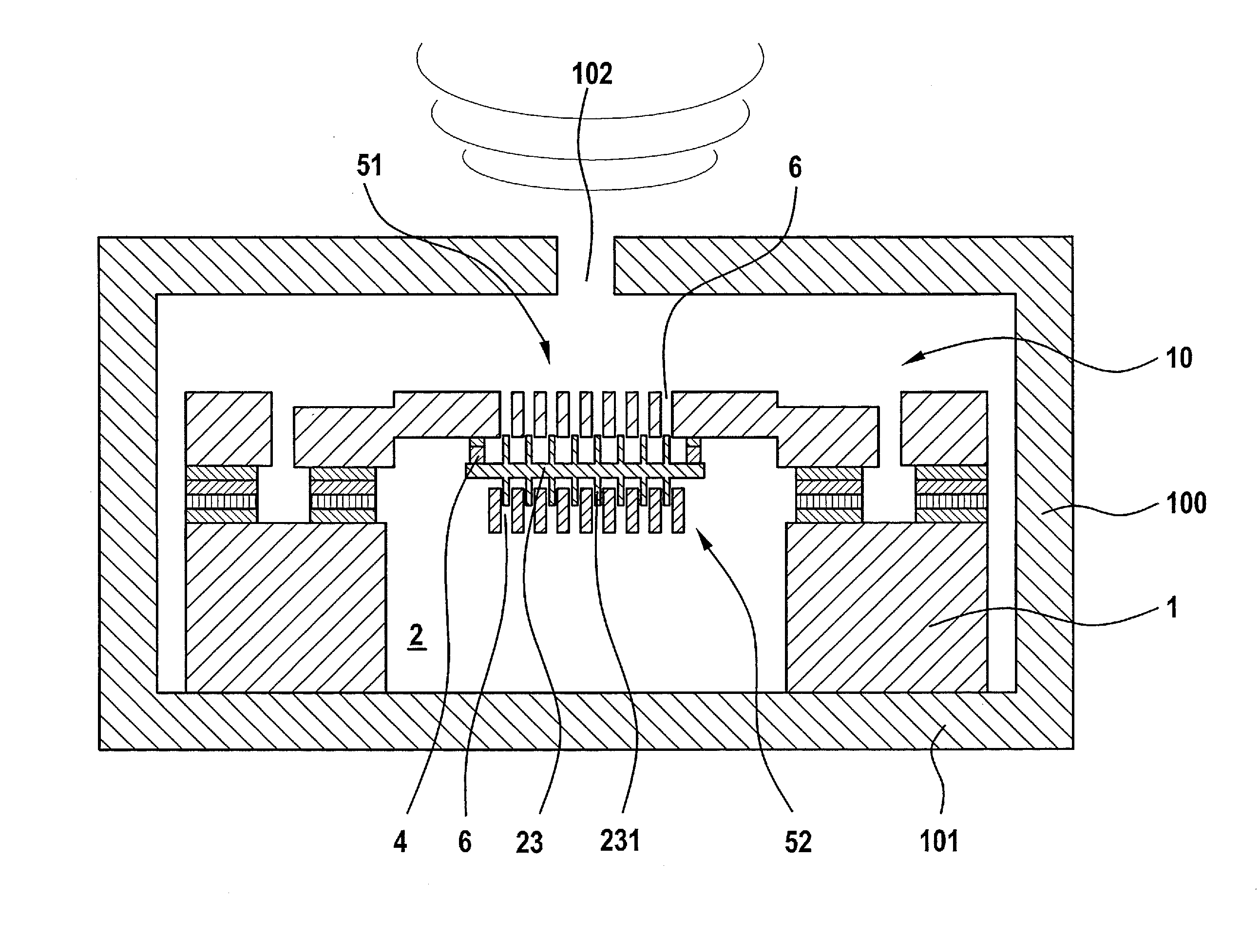
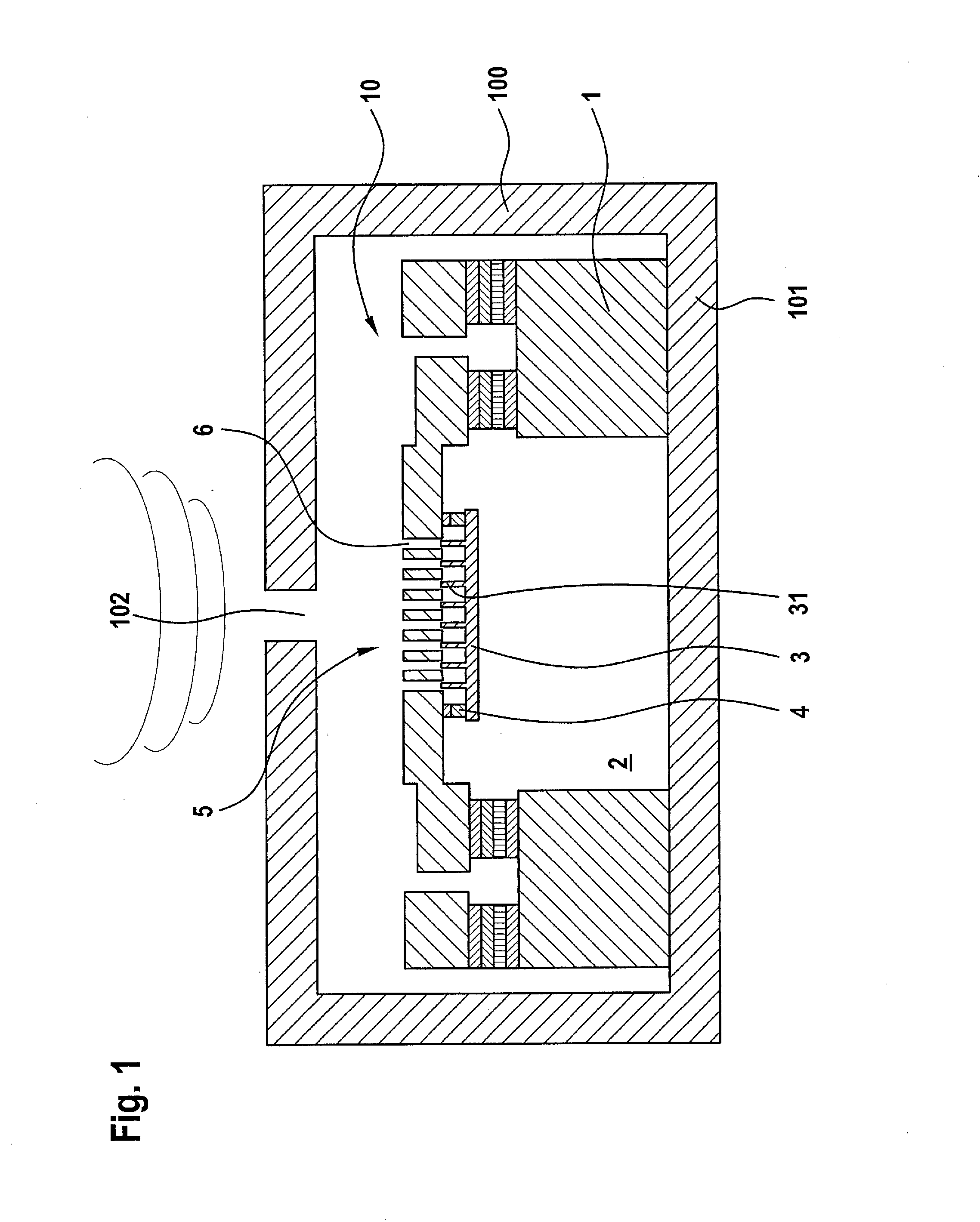
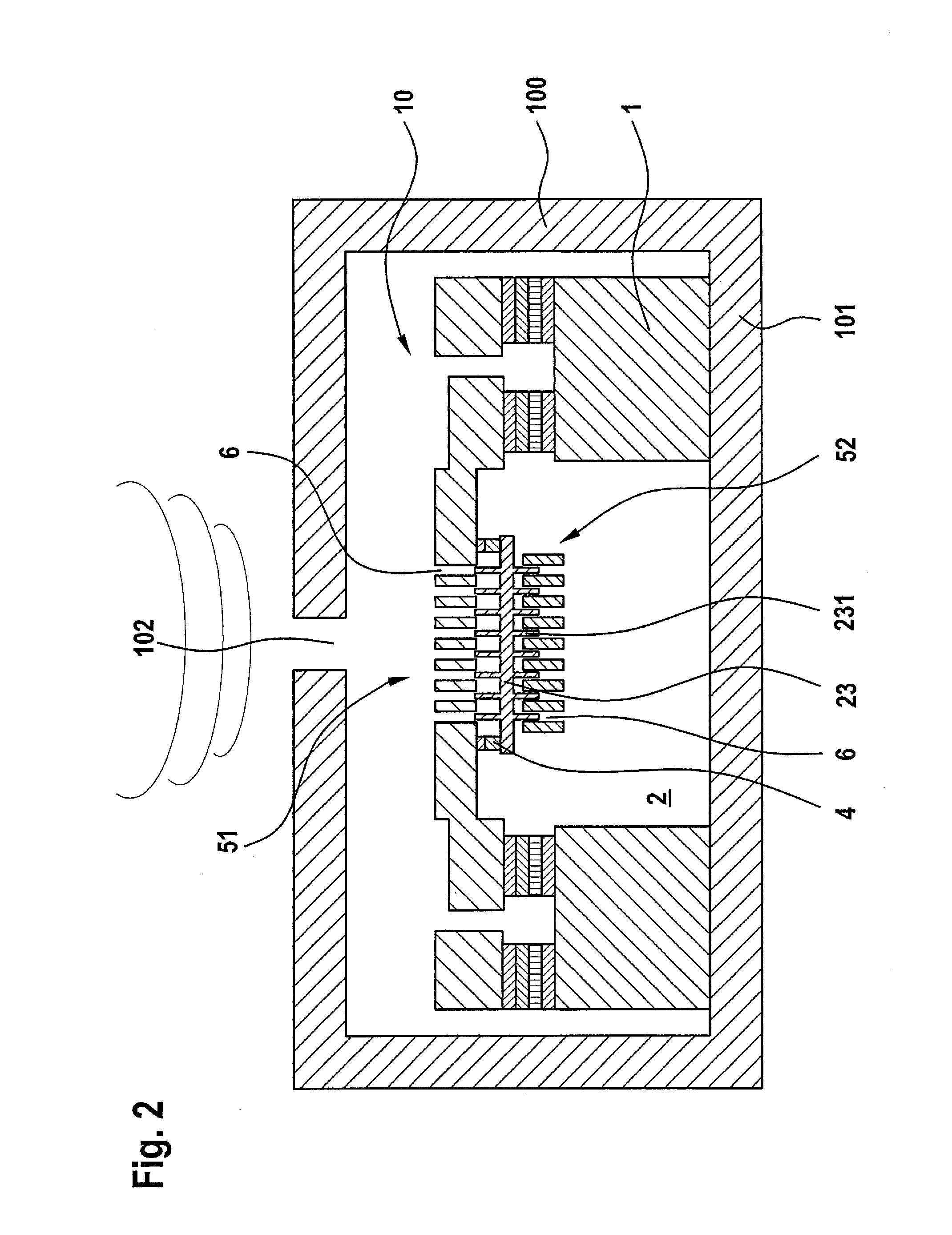
[0024]Microphone component 10 shown in FIG. 1 is a MEMS component which is realized in a layer construction, starting from a substrate 1. The microphone structure of component 10 overspans a cavity 2 in the back side of the substrate. It includes a diaphragm structure 3 sensitive to sound pressure, which is deflectable in a direction essentially perpendicular to the layer planes of the layer construction, thus, out-of-plane. The microphone structure also includes an acoustically penetrable counter-element 5 having through holes 6. In the exemplary embodiment shown here, counter-element 5 is disposed above diaphragm structure 3 in the layer construction.

[0025]Diaphragm structure 3 is connected to counter-element 5, and specifically, via spring elements 4 which are formed in the edge area of diaphragm structure 3. In an exemplary embodiment not shown, diaphragm structure 3 may also be disposed above counter-element 5.

[0026]According to the invention, diaphragm structure 3 includes str...


PUM


Abstract

A capacitive MEMS microphone structure is provided, which micromechanical microphone structure of component is realized in a layer construction and includes: a diaphragm structure sensitive to sound pressure, which is deflectable in a direction perpendicular to the layer planes of the layer construction; an acoustically penetrable counter-element which has through holes and is formed above or below the diaphragm structure in the layer construction; and a capacitor system for detecting the excursions of the diaphragm structure. The diaphragm structure includes a structural element in the middle area of the diaphragm structure, which structural element projects perpendicularly from the diaphragm plane and which, depending on the degree of excursion of the diaphragm structure, variably extends into a correspondingly formed and positioned through hole in the counter-element.

Description

BACKGROUND OF THE INVENTION[0001]1. Field of the Invention[0002]The present invention relates to a component having a micromechanical microphone structure which is realized in a layer construction. The microphone structure includes at least one diaphragm structure which is sensitive to sound pressure and is deflectable essentially in a direction perpendicular to the layer planes of the layer construction; an acoustically penetrable counter-element having through holes, which is formed above or below the diaphragm structure in the layer construction; and a capacitor system for detecting the excursions of the diaphragm structure.[0003]2. Description of the Related Art[0004]MEMS (Micro-Electro-Mechanical-System) microphones of the type discussed here have been known for years and are employed within the framework of widely varying practical applications.[0005]MEMS microphones are common which have a flat diaphragm structure that is parallel to the chip or substrate plane and is excited...

Claims


Application Information

Patent Timeline
Patent Type & Authority Applications(United States)
IPC IPC(8): H04R23/00
CPCH04R23/00H04R19/005H04R19/04H04R2410/03H04R7/14
Inventor ZOELLIN, JOCHENEHRENPFORDT, RICARDOGRAF, JUERGENSCHELLING, CHRISTOPHANTE, FREDERIKCURCIC, MICHAEL
Owner ROBERT BOSCH GMBH
Why Eureka
Try Eureka