Motor vehicle component that withstands thermal deformation

a technology for motor vehicles and components, applied in the field of motor vehicle bodywork parts, can solve the problems of limited choice, defects, and plastic material defects, and achieve the effects of low cost, reduced manufacturing costs, and reduced manufacturing costs

a technology for motor vehicles and components, applied in the field of motor vehicle bodywork parts, can solve the problems of limited choice, defects, and plastic material defects, and achieve the effects of low cost, reduced manufacturing costs, and reduced manufacturing costs

US20140105669A1Inactive Publication Date: 2014-04-17CO PLASTIC OMNIUM

Image

  • Motor vehicle component that withstands thermal deformation
  • Motor vehicle component that withstands thermal deformation

Examples


Embodiment Construction

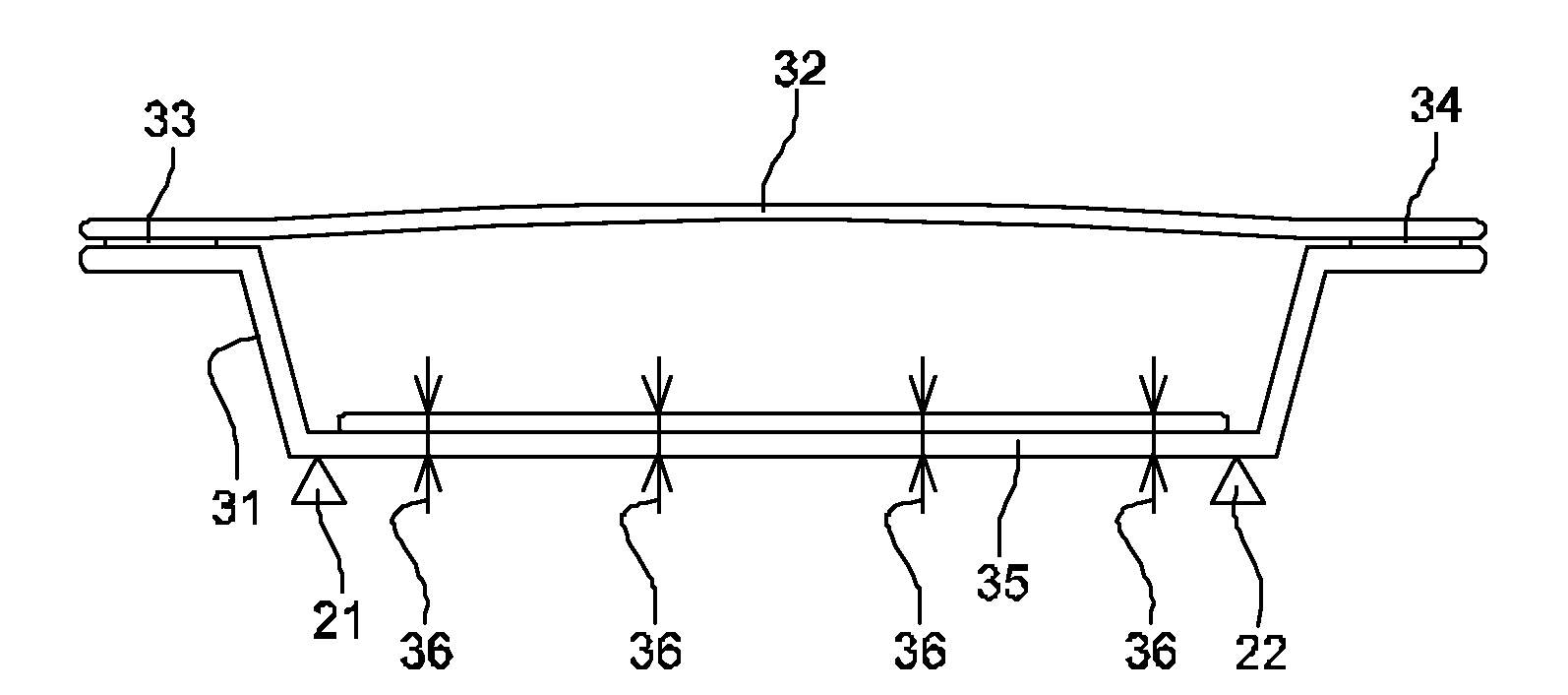
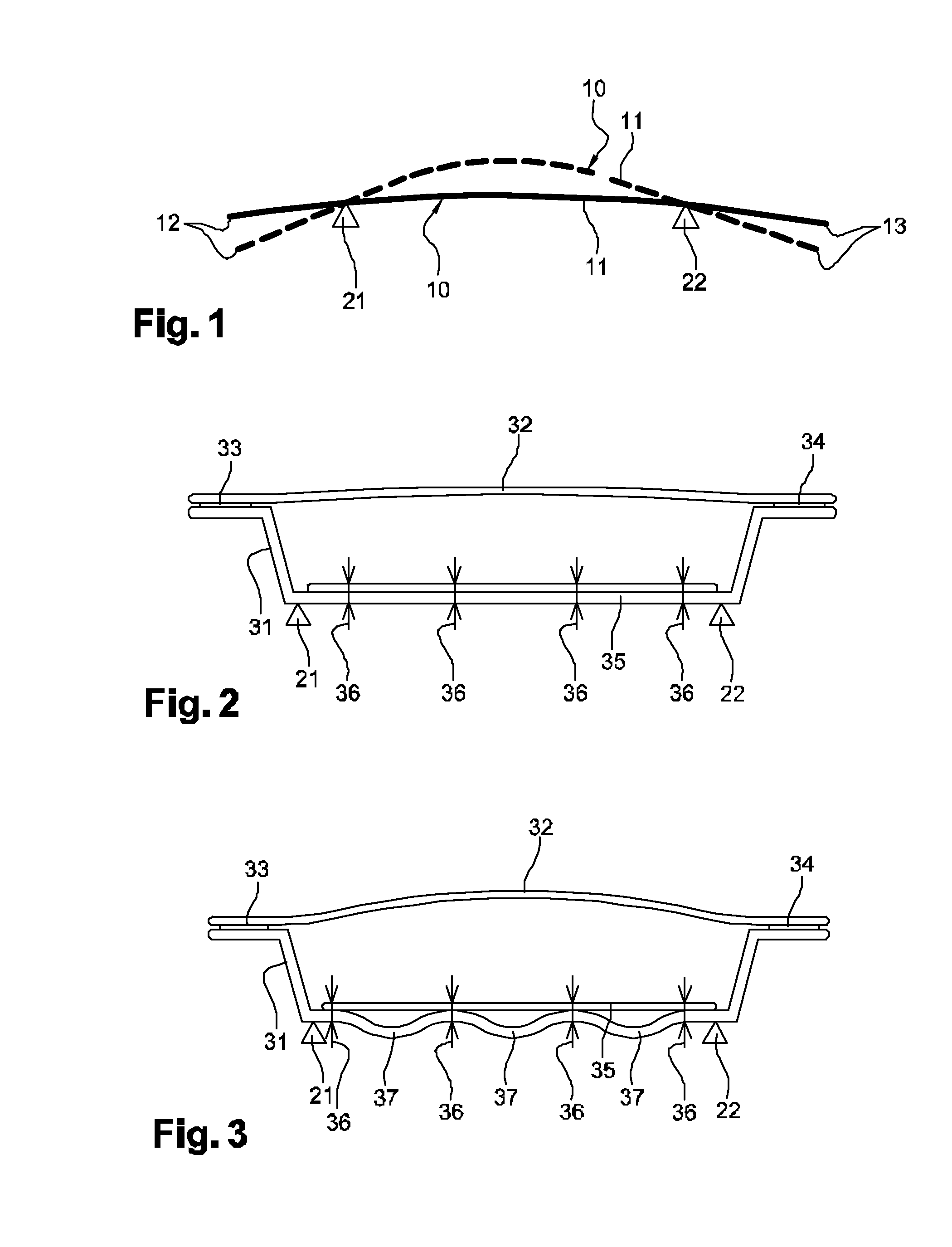
[0033]FIG. 1 is a diagrammatic view of a motor vehicle bodywork component. In this example, the component is a structure 10 represented by a continuous line in a situation in which it is not subjected to any expansion, and by a dashed line in a situation where it is exposed to intense solar radiation.

[0034]The structure 10 is fastened to the body of the vehicle by two hinges 21 and 22 represented by triangles. Since the body of the vehicle is made of a material having a smaller coefficient of expansion than the structure 10, the hinges 21 and 22 are spaced apart by a distance that is constant under both of the presently-considered situations, with or without sunshine. Thus, the structure 10 presents a central portion 11 situated between the hinges 21 and 22, which central portion 11 is subjected to stress horizontally by the hinges 21 and 22. An expansion of this central portion 11 thus gives rise to the vehicle being outwardly deformed in bending or “bulging”. By continuity, the ma...


PUM

PropertyMeasurementUnit
thicknessaaaaaaaaaa
thicknessaaaaaaaaaa
thicknessaaaaaaaaaa

Abstract

The invention relates to a motor vehicle bodywork component comprising a first panel and a second panel having a second coefficient of linear thermal expansion greater than the first coefficient of linear thermal expansion of the first panel, the component further including a connection part having a third coefficient of linear thermal expansion that is less than the first and that is fastened to the first panel.

Description

CROSS-REFERENCE TO RELATED APPLICATIONS[0001]This application claims priority to French Application No. 1259912 filed Oct. 17, 2012, and to European Application No. 13166647.1 filed May 6, 2013, which applications are incorporated herein by reference and made a part hereof.BACKGROUND OF THE INVENTION[0002]1. Field of the Invention[0003]The present invention relates to motor vehicle bodywork parts, whether they be static parts or opening members.[0004]2. Description of the Related Art[0005]Most bodywork parts are made of metal sheet, usually steel sheet. Bodywork parts made of plastics material are becoming more and more widespread, such as bumpers, tailgates, fenders, etc., which parts coexist at their interfaces with other parts that are still made of metal, such as fenders, hoods, doors, etc.[0006]Such parts made of plastics material may present defects that are particularly visible in an outside panel because the panel can be seen from the outside, and defects show up in particul...

Claims


Application Information

Patent Timeline
17 Apr 2014
Publication
US20140105669A1
IPC
B62D27/00; B62D29/00
CPC
B62D29/00; B62D27/00; B60J5/0481; B62D25/00; B62D27/02; B62D29/04; Y10T403/217
Inventors
COUDRON, PHILIPPE