Lockable connection device with closed ring to hold an object, such as a key, dog tag, and the like
Active Publication Date: 2014-04-24
AHA LLC
View PDF6 Cites 2 Cited by
Summary
Abstract
Description
Claims
Application Information
AI Technical Summary
This helps you quickly interpret patents by identifying the three key elements:
Problems solved by technology
Method used
Benefits of technology
Benefits of technology
The present invention is about a connection device for holding objects, like keys or dog tags. It includes a loop and a body. The loop has a part that hangs out, and the body is attached to this part. The loop has a part that sticks out, creating a space between the loop and the end to hold the object. The body has a part that attaches to the loop. This part sticks out from the body and forms a space to hold the object. The two parts have shapes that fit together and prevent the object from moving too far out.
Problems solved by technology
Conventional split ring connectors are difficult to pry open and often require the use of a tool or fingernail, which can lead to injury.
However, conventional ring-type connectors have various deficiencies.
For instance, such connectors have rings with exposed ends that can be inadvertently snagged or caught by an adjacent object.
The exposed ends of conventional connectors can also be flexed such that the connector is unintentionally opened.
For example, inadvertent contact between the exposed end and an adjacent object can cause the exposed end to flex and open the connector.
However, forces purposely applied to the connector can also cause inadvertent opening of the connector.
This problem of unintended ring flexure is particularly acute when the pulling force is applied adjacent to the exposed end of the ring.
Method used
Image
Click on the blue label to locate the original text in one second.
Reading with bidirectional positioning of images and text.
Examples
Embodiment Construction
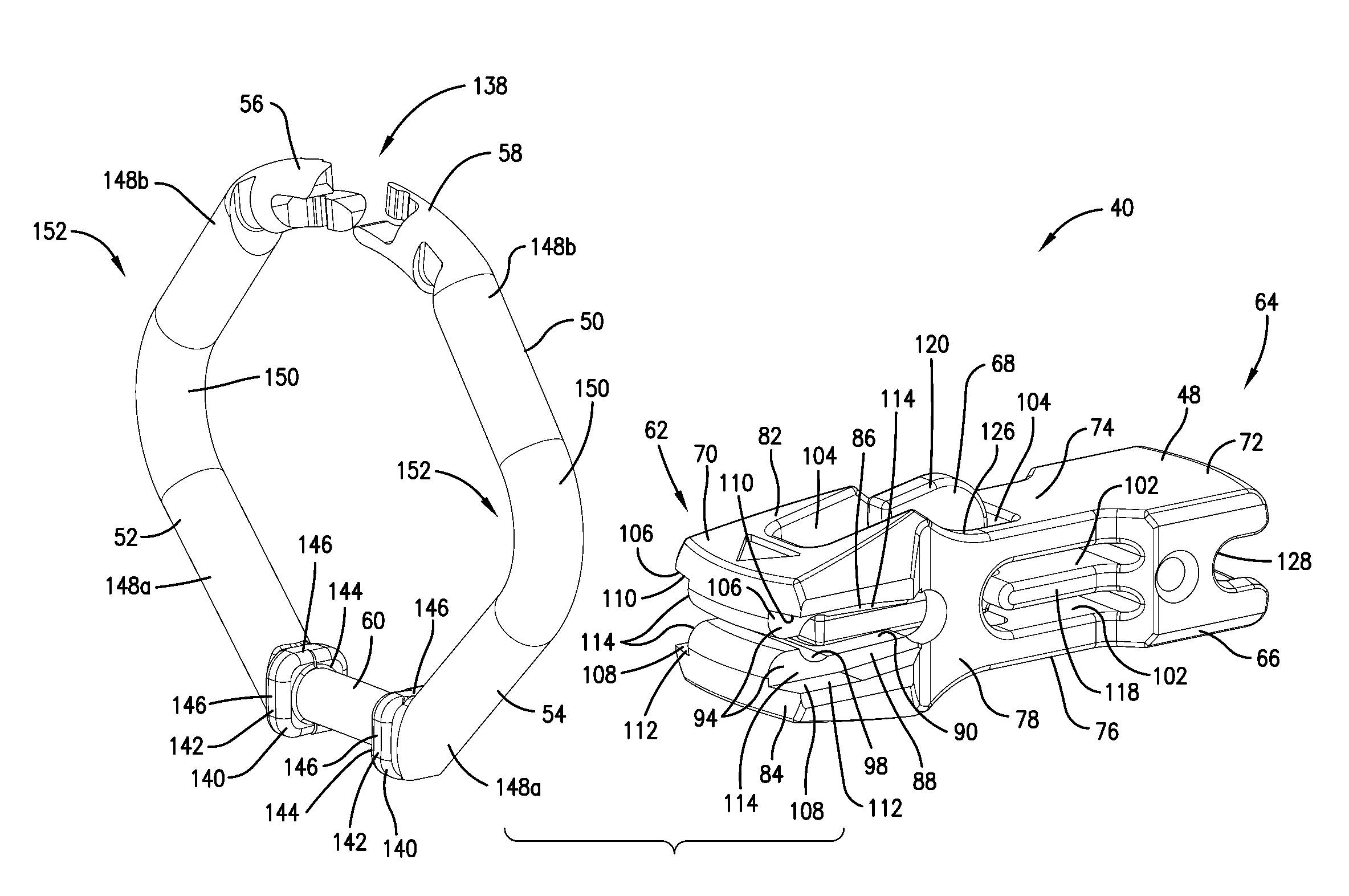
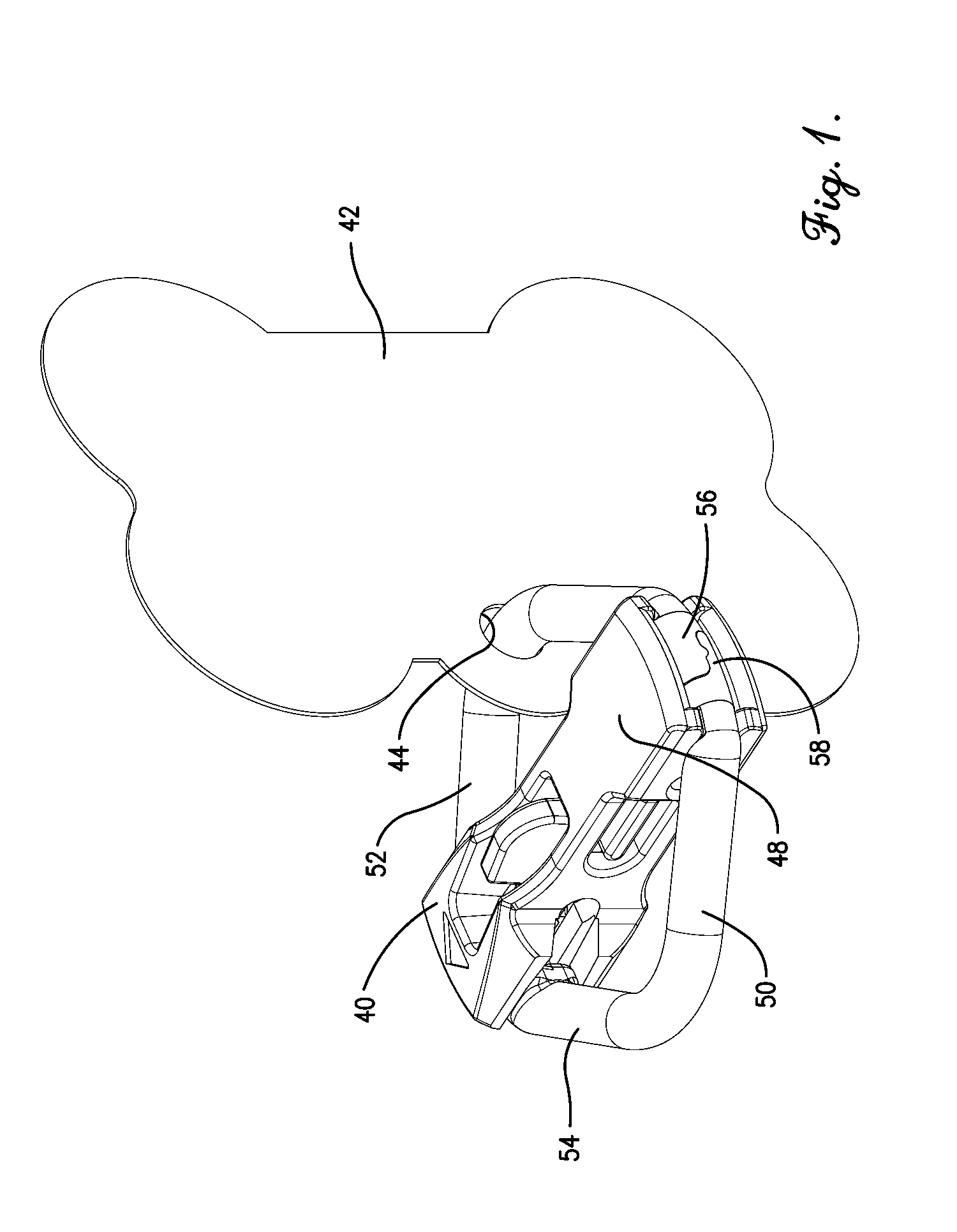
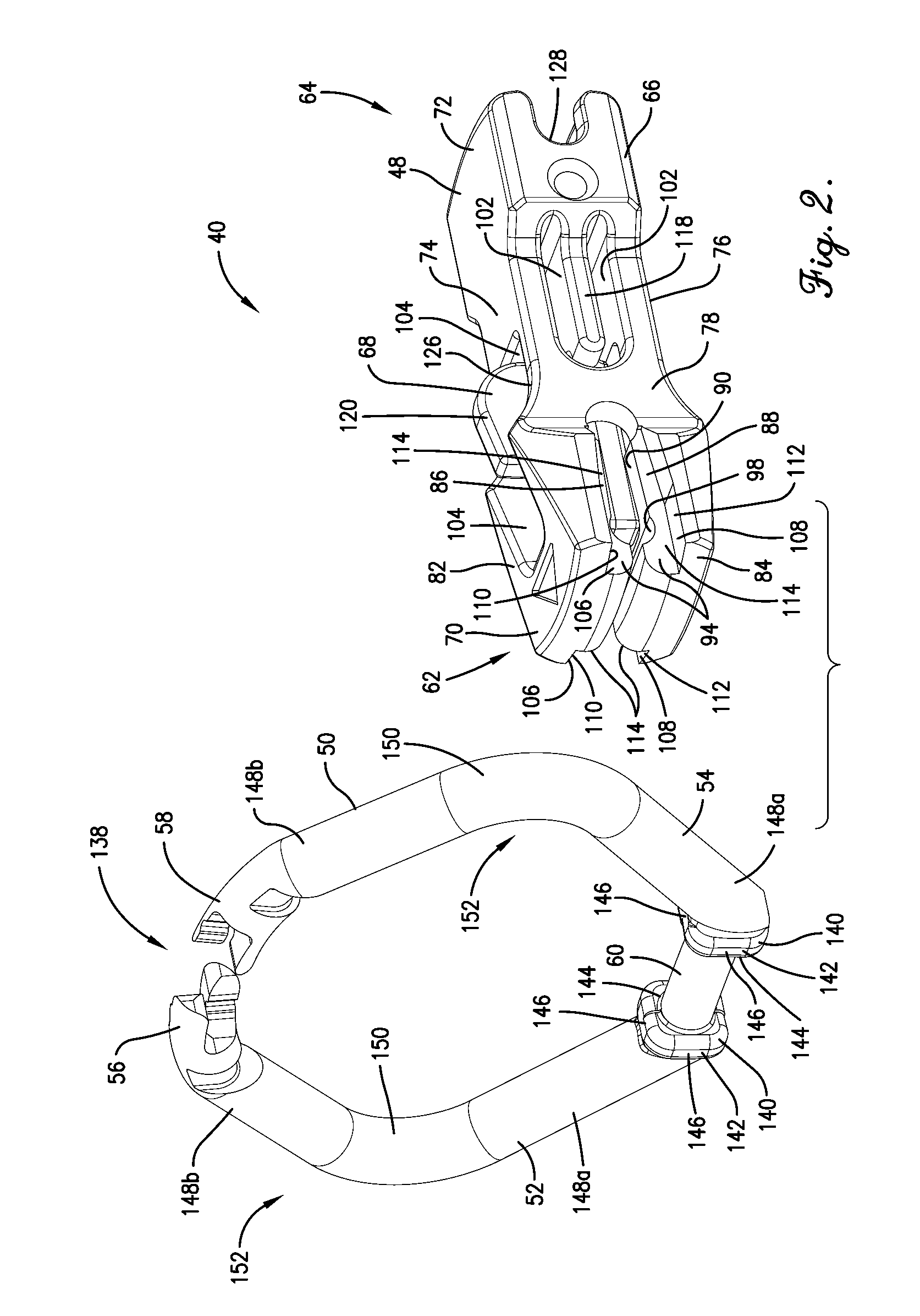
[0034]Turning initially to FIGS. 1 and 2, a connection device 40 is constructed in accordance with a preferred embodiment of the present invention. The connection device 40, also referred to herein as connector 40, may hold various types of objects such as, for instance, keys, key fob tags, dog tags, or the like. The connector 40 shown in FIG. 1 is in a closed condition in which a dog tag 42 is retained thereon. The tag 42 is conventional and contains a through-hole 44 in a tab presented by the tag 42. The through-hole 44 is configured to receive the ring 50 therein to operatively interconnect the connector 40 and tag 42 together. The illustrated connector 40 broadly includes a body 48 and a ring 50.
[0035]The body 48 preferably bisects the ring 50 into two arcuate ring portions 52,54 that preferably terminate at respective ends 56,58 and extend from a ring hinge portion 60 (e.g., see FIG. 2). While the embodiments of the connector 40 shown herein involve a body 48 that bisects the r...
PUM
Abstract
A connection device is operable to hold an object, such as a key, dog tag, and the like. The connection device broadly includes a ring and a body. The ring includes a ring end and is coupled to the body at a connection location spaced from the end. The ring presents a projecting ring portion defined between the connection location and the ring end. The projecting ring portion cooperates with the body to define therebetween a space so as to accommodate the object. The body includes an end-engaging portion spaced from the connection location. The ring end is engageable with the end-engaging portion of the body to secure the object on the projecting ring portion.
Description
RELATED APPLICATION[0001]This application claims the benefit of U.S. Provisional Application Ser. No. 61 / 717,307, filed Oct. 23, 2012, entitled LOCKABLE CONNECTION DEVICE WITH CLOSED RING TO HOLD AN OBJECT, SUCH AS A KEY, DOG TAG, AND THE LIKE, and U.S. Provisional Application Ser. No. 61 / 755,320, filed Jan. 22, 2013, entitled LOCKABLE CONNECTION DEVICE WITH CLOSED RING TO HOLD AN OBJECT, SUCH AS A KEY, DOG TAG, AND THE LIKE, each of which is hereby incorporated in its entirety by reference herein.BACKGROUND[0002]1. Field[0003]The present invention relates generally to connection devices. More specifically, the present invention concerns connection devices for holding objects, such as, for instance, keys or dog tags.[0004]2. Discussion of Prior Art[0005]Various types of ring-type connectors have long been employed to hold keys, tags, and other small objects for convenient storage and access. Such connectors typically include a circular, wire-type ring that can be selectively opened ...
Claims
Application Information
Patent Timeline
Application Date:The date an application was filed.
Publication Date:The date a patent or application was officially published.
First Publication Date:The earliest publication date of a patent with the same application number.
Issue Date:Publication date of the patent grant document.
PCT Entry Date:The Entry date of PCT National Phase.
Estimated Expiry Date:The statutory expiry date of a patent right according to the Patent Law, and it is the longest term of protection that the patent right can achieve without the termination of the patent right due to other reasons(Term extension factor has been taken into account ).
Invalid Date:Actual expiry date is based on effective date or publication date of legal transaction data of invalid patent.
