
Floating floor assembly for armored vehicles

Active Publication Date: 2014-04-24
BAE SYSTEMS LAND & ARMAMENTS LP
View PDF7 Cites 6 Cited by
  • Summary
  • Abstract
  • Description
  • Claims
  • Application Information

AI Technical Summary

Benefits of technology

The present invention is about a flooring assembly for a vehicle that reduces the risk of damage from explosive events to the crew compartment. The flooring panels are mounted on the sides of the vehicle to float above the belly armor, eliminating structural conduits through which explosive energy can be transmitted. A torsion bar strap can be positioned between the support beams to absorb and further dissipate the explosive energy. The floating floor also captures shrapnel from the explosion using a containment blanket. The invention can provide a safer environment for the crew in the event of an explosive event.

Problems solved by technology

In addition, the explosive energy must travel through the significantly thicker side armor paneling, which can dissipate the explosive energy over a greater amount of material.

Method used


Image

  • Floating floor assembly for armored vehicles
  • Floating floor assembly for armored vehicles
  • Floating floor assembly for armored vehicles

Examples


Embodiment Construction

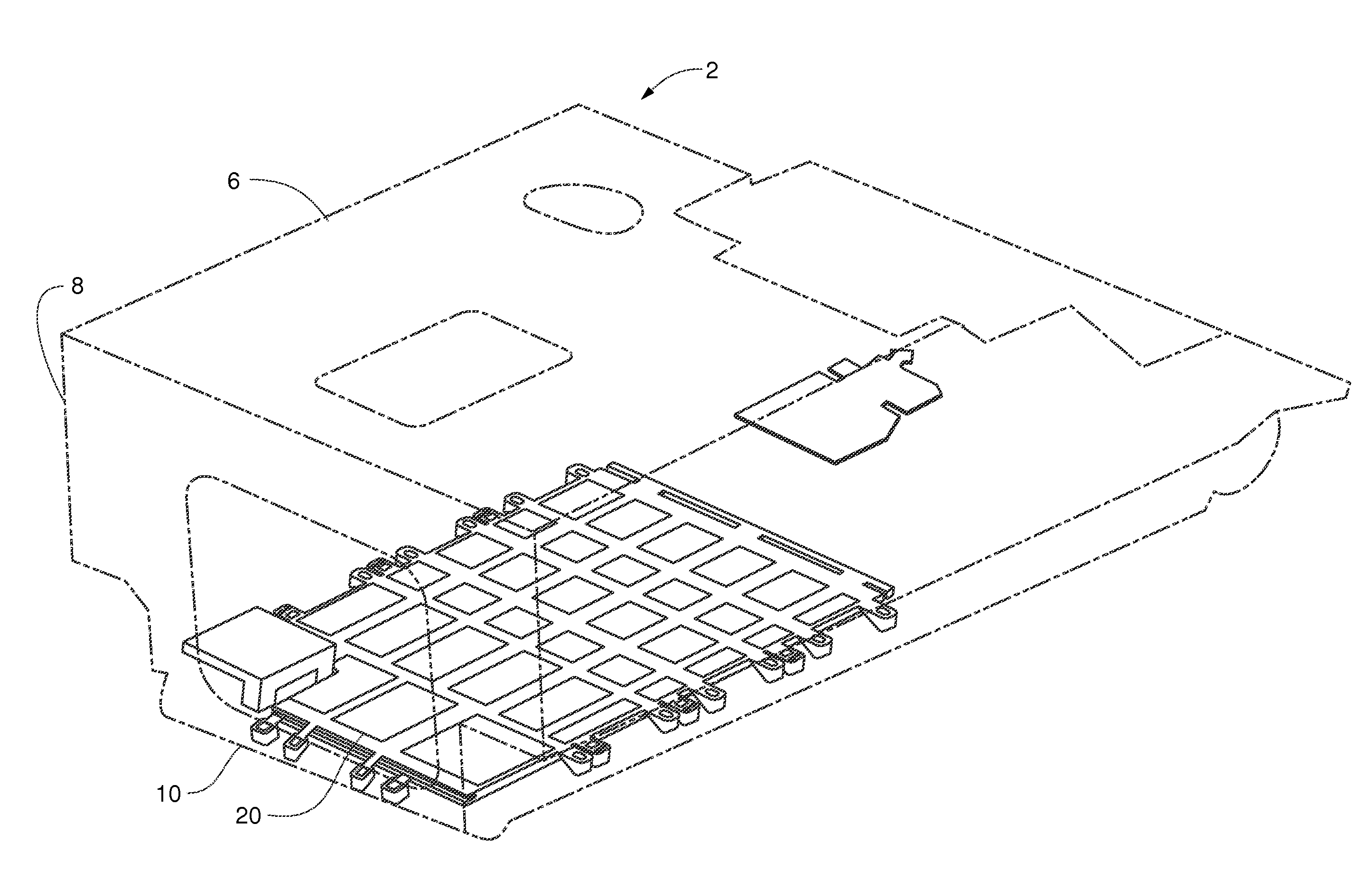
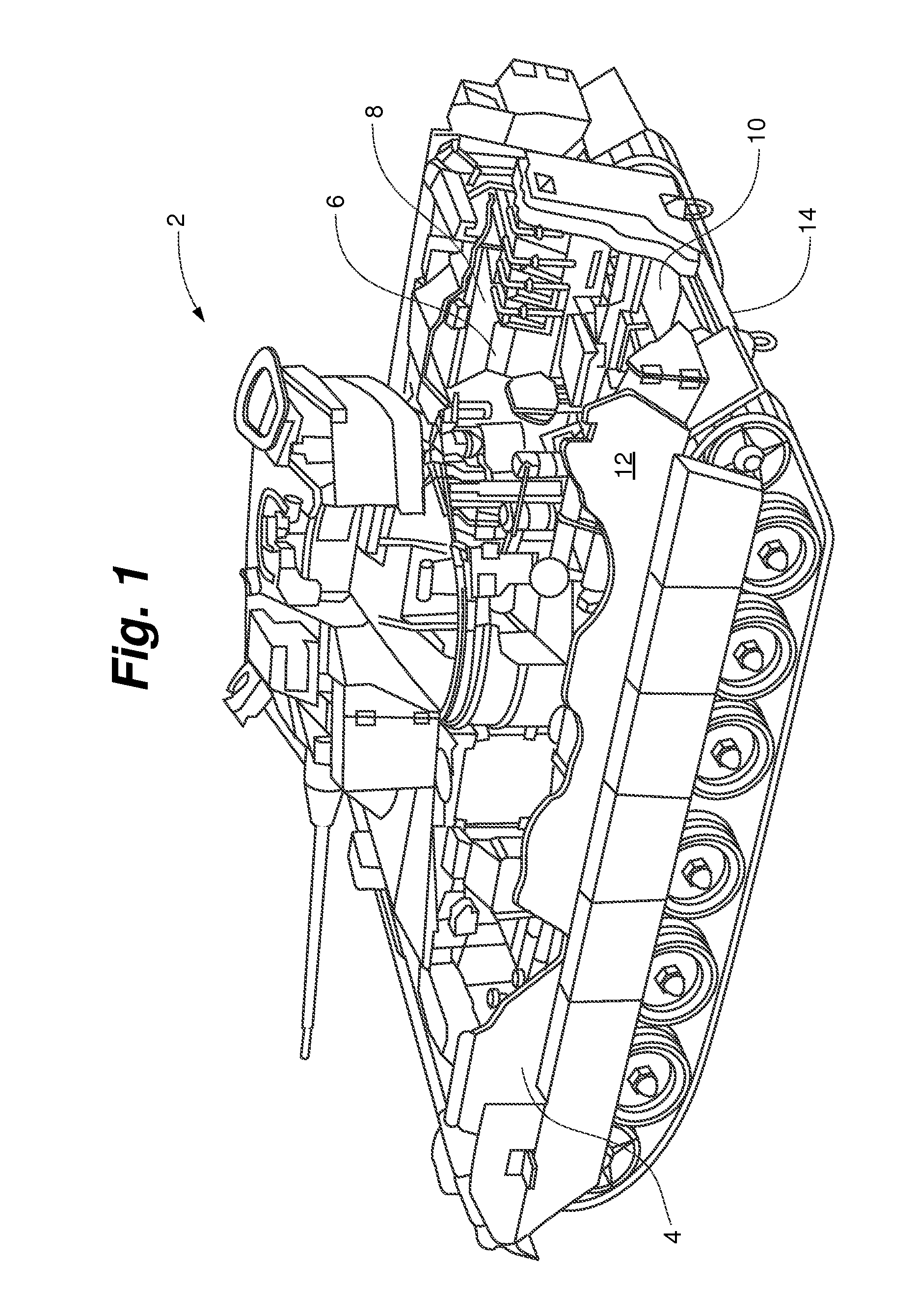
[0024]As shown in FIG. 1, a vehicle 2 for use with the present invention can generally comprise a crew compartment 6 and an armored hull 4. The crew compartment 6 can further comprise at least two opposing sidewalls 8 and a floor 10. Similarly, the armored hull 4 can further comprise at least two opposing side armor sections 12 and a belly armor section 14 positioned beneath the floor 10. As depicted, the vehicle 2 is a Bradley Infantry Fighting Vehicle (IFV), but can comprise any wheeled or tracked armored vehicle.

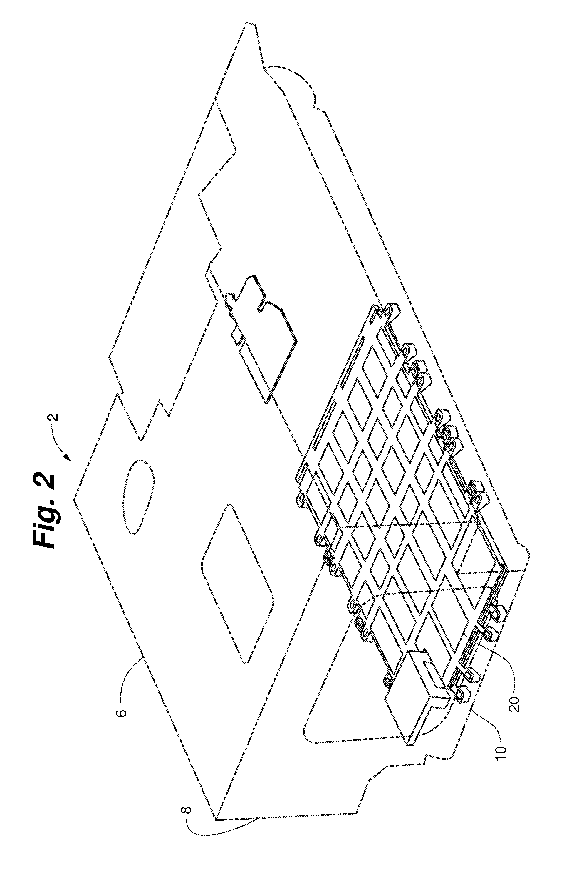
[0025]As shown in FIGS. 2-3 and 5, a floating floor system 20 comprises a support assembly 24 and at least one flooring panel 26. The support assembly 24 can further comprise at least two primary support beams 28 each having a wall mount 30 adapted to receive a fastener 32 and affixed to each end of the support beam 28. In one aspect, at least one wall mount 30 can be positioned at each end of each primary support beam 28. Each flooring panel 26 can further comprise at le...


PUM


Abstract

A floating floor assembly for an armored vehicle mounted to the sides of the vehicle to suspend the floor above the belly armor of the vehicle rather than being directly supported by the belly armor. The floating floor reduces the amount of energy that is transferred by the floating floor from the belly plate and further reduces the risk that any deformation of the belly armor from the explosion will cascade to the floating floor causing the floor to buckle or fragment into secondary shrapnel.

Description

RELATED APPLICATION[0001]The present application claims the benefit of U.S. Provisional Application No. 61 / 531,816, filed Sep. 7, 2011, which is incorporated herein by reference in its entirety.FIELD OF THE INVENTION[0002]The present invention is generally directed to a floor assembly for an armored vehicle. Specifically, the present invention is generally directed to a floating floor assembly that suspends the flooring above the belly armored minimizing the effect of an explosive event originating beneath the vehicle on the crew compartment.BACKGROUND OF THE INVENTION[0003]An armored vehicle typically comprises armor paneling mounted on the sides, roof and the bottom of the vehicle. The substantial weight of the armor paneling creates a tradeoff between the operational weight of the vehicle that can be effectively handled by the engine versus the amount of armor necessary to protect the occupants and critical systems of the vehicle. Accordingly, the vehicle armor is typically conce...

Claims


Application Information

Patent Timeline
IPC IPC(8): F41H5/013F41H7/04
CPCF41H7/042F41H5/013B62D25/20
Inventor AKAVUTI, RON V.SHMARGAD, AMIKAM
Owner BAE SYSTEMS LAND & ARMAMENTS LP
Learn More