Motor drive device

Active Publication Date: 2014-04-24
NTN CORP
View PDF1 Cites 32 Cited by
  • Summary
  • Abstract
  • Description
  • Claims
  • Application Information

AI Technical Summary

Benefits of technology

[0038]In the case where there are plurality of wheels 2 that are individually motor-driven, when a malfunction of the motor rotor angle sensor 36 occurs during travelling, an imbalance is produced in torque, which may cause a slip or skid. Thus, it is more effective to switch to control based on the angle estimation value from the wheel speed based motor rotor angle estimator 46 or the sensorless angle estimator 50. In addition, in the case of an electric vehicle including a plurality of motor units 6, it is made easy to utilize the start-up rotor angle calculator 102 which uses the above motor counter electromotive force.
[0039]The in-wheel motor system 8 may include a wheel bearing unit 4, the motor unit 6, and a reducer unit 7 interposed between the motor unit 6

Problems solved by technology

In a motor drive device t sensed hat performs control based on the position of magnetic poles of a motor rotor as described in Patent Document 1 and Patent Document 2 listed above, when damage of an angle sensor for the motor rotor, breaking of a wire thereof, or the like occurs, an angle detection value cannot be properly recognized, and driving of the motor is no longer possible.
Or, occurrence of desired tor

Method used


Image

  • Motor drive device
  • Motor drive device
  • Motor drive device

Examples


first embodiment

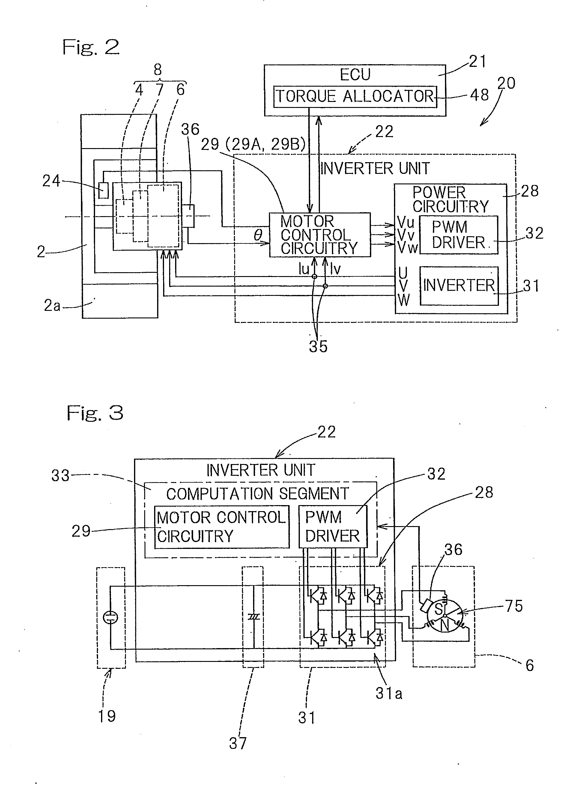
[0086]The motor drive device 20 may include the general drive controller 38 having the above configuration, and may further include a sensorless angle estimator (first motor rotor angle estimator) 50 and a sensor malfunction determination sensor switching unit 47 as shown in FIG. 5. The sensorless angle estimator 50 may be configured to estimate an angle of the motor rotor without using a rotation sensor, and may include a phase estimator 50a, a first comparison segment 50b, and a correction value storage / corrector 50c. The sensor malfunction determination sensor switching unit 47 may include a sensor malfunction determiner 47a that may be configured to determine a malfunction of the motor rotor angle sensor 36; and a sensor switcher 47b that may be configured to cause the general drive controller 38 to perform control using an estimation value indicating a motor rotor angle produced from the sensorless angle estimator 50 instead of the angle detection value sensed by the motor rot...

third embodiment

[0124]The motor drive device 20 may include the multiplication processing segment 46b, and the wheel speed based motor rotor angle estimator 46 may be configured to multiply pulses produced from the wheel rotational frequency sensor 24 and to estimate an angle of the motor rotor. Thus, high resolution is obtained even by the wheel speed based motor rotor angle estimator 46. Since the wheel rotational frequency sensor 24 is used in an anti-lock-braking system or the like, high resolution is in general unnecessary for the wheel rotational frequency sensor 24, and a sensor having lower resolution than that of the motor rotor angle sensor 36 is used as the wheel rotational frequency sensor 24. However, in the case where the wheel rotational frequency sensor 24 is configured to calculate intervals between pulses and to sense a rotation speed of the wheel, it is possible to improve the resolution of a detected angle by multiplying the pulses, and it is possible to obtain the similar leve...

fifth embodiment

[0133]A sensor malfunction determination sensor switching unit 47A of the motor control circuitry 29B of the motor drive device 20 may include a sensor malfunction determiner 47Aa that may be configured to determine malfunctions of the motor rotor angle sensor 36 and the wheel rotational frequency sensor 24, and a sensor switcher 47Ab. When the sensor malfunction determiner 47Aa determines that the motor rotor angle sensor 36 malfunctions, the sensor switcher 47Ab may cause the general drive controller 38 to perform control using the motor rotor angle produced from the wheel speed based motor rotor angle estimator 46 instead of the angle detection value sensed by the motor rotor angle sensor 36 (FIG. 15A). Moreover, when the sensor malfunction determiner 47Aa determines that the wheel rotational frequency sensor 24 malfunctions, the sensor switcher 47Ab may cause the general drive controller 38 to perform control using the motor rotor angle produced from the sensorless angle estima...


PUM


Abstract

A motor drive device is provided which allows control to be performed depending on a position of magnetic poles of a rotor even when a motor rotor angle sensor malfunctions. The device controls a motor for driving a wheel of an electric vehicle, depending on the position of the magnetic poles by using an angle sensed by the angle sensor provided at the motor. The device includes an estimator estimating an angle of a rotor of the motor without using a rotation sensor; a sensor malfunction determiner determining a malfunction of the angle sensor; and a switcher causing control to be performed using a angle estimated by the estimator instead of the angle sensed by the angle sensor once the determiner determines that the angle sensor malfunctions.

Description

CROSS REFERENCE TO THE RELATED APPLICATION[0001]This application is based on and claims the Convention priority to a Japanese patent application Nos. 2011-145559, filed Jun. 30, 2011, 2011-149944, filed Jul. 6, 2011, and 2011-149945, filed Jul. 6, 2011, the entire disclosures of which are herein incorporated by reference as a part of this application.BACKGROUND OF THE INVENTION[0002]1. Field of the Invention[0003]The present invention relates to a motor drive device that may control a motor for driving a wheel in an electric vehicle.[0004]2. Description of Related Art[0005]In an electric vehicle, for efficiently driving a motor, control is performed based on the position of magnetic poles of a motor rotor, using an angle sensor which may be configured to sense an angle of the motor rotor. As this control, for example, field oriented control or vector control is used (Patent Document 1 and Patent Document 2).PRIOR ART DOCUMENT[0006][Patent Document 1] JP Laid-open Patent Publication ...

Claims


Application Information

Patent Timeline
IPC IPC(8): H02P6/18
CPCH02P6/18B60L3/0038B60L2220/44B60L3/0084B60L3/102B60L3/108B60L3/12B60L7/14B60L15/2009B60L2220/14B60L2240/421B60L2240/423B60L2240/427B60L2240/429B60L2240/461B60L2260/44B60L50/51Y02T10/64Y02T10/70Y02T10/72H02K29/08H02P6/181H02P6/182H02P6/20
Inventor YAMADA, HIROYUKI
Owner NTN CORP
Why Eureka
Try Eureka