Co-registration of cores in multicore optical fiber sensing systems

a multi-core optical fiber and core technology, applied in the field of multi-core optical fiber, can solve the problems of increasing the complexity of the method of co-registration, the loss of co-registration is unpredictable, and the optical delay in each core can change, so as to reduce the effect of bi-refringen

Active Publication Date: 2014-04-24
INTUITIVE SURGICAL OPERATIONS INC
View PDF3 Cites 19 Cited by
  • Summary
  • Abstract
  • Description
  • Claims
  • Application Information

AI Technical Summary

Benefits of technology

[0015]A twisted, multicore fiber communicates light input to each core to an output. The twisting mitigates relative time delays of the input light traveling through each of the cores in the multicore fiber to the output caused by bending of that multicore fiber. An example application is in an optical network that includes an optical input terminal and an optical sensor connected by a twisted multicore connecting fiber. One example of twisted multicore optical fiber is helically-wrapped, multicore fiber.
[0016]One aspect of the technology includes a method for reducing a variable level of optical skew in an optical network including an optical input terminal and an optical sensor. The optical input terminal and the optical sensor are connected using a twisted multicore fiber. Relative time delays of light traveling through each of the cores in the multicore connecting fiber are compensated for using the twist in the multicore fiber. The relative time delays of light are caused by one or more bends in the twisted multicore fiber and may depend on a shape of the twisted multicore fiber when connecting the optical input terminal and the optical sensor. The twisted multi-core fiber mitigates variable levels of optical skew in the light traveling to the optical sensor to provide co-registered light at the optical sensor.
[0017]Another aspect of the technology is a twisted, multicore optical fiber for communicating light input to each core to an output. The twisting of the multicore optical fiber mitigates relative time delays of the input light traveling through each of the cores in the twisted, multicore optical fiber to the output caused by bending of the twisted, multicore optical fiber.
[0020]In a non-limiting example embodiment, the twist has a consistent direction along the length of the twisted multicore fiber. Moreover, a number of twists per unit distance along the twisted multicore fiber exceeds a number of twists per unit distance along the twisted multicore fiber to reduce effects of birefringence.

Problems solved by technology

As practical systems are constructed and exposed to environmental influences, the method of co-registration becomes increasingly complicated.
Application of tension, compression, or temperature change may also cause changes to the optical delay in each core to a fixed point on the fiber.
When the multicore connecting fiber is bent or twisted, different dynamic strains are induced in each core of the multicore fiber, and an unpredictable loss of co-registration can occur in the multicore sensing region that varies with time as the multicore connecting fiber is moved.
So even though the fiber cores in the multicore connecting fiber enter the multicore sensing region at the same physical location, the dynamic optical delay differences in the bent multicore connecting fiber caused by the compression and elongation result in a loss of co-registration that can no longer be compensated using static optical delay corrections referenced above.
However, this is undesirable because it requires time intensive calculations over regions for which such calculation is not required by the shape sensing application, i.e., there is no need to perform shape sensing calculations for the multicore connecting fiber.
So this approach slows down the operation of a shape sensing system and increases its cost.
But this alternative requires added complexity, time-consuming algorithms, possible optical component adjustments, and added cost.
The ability to accurately sense shape for such a system is also limited by how well the registration can be maintained, and the accurate response to a changing shape may depend on the speed of the co-registration detection and compensation scheme.

Method used


Image

  • Co-registration of cores in multicore optical fiber sensing systems
  • Co-registration of cores in multicore optical fiber sensing systems
  • Co-registration of cores in multicore optical fiber sensing systems

Examples


Embodiment Construction

[0037]The following description sets forth specific details, such as particular embodiments for purposes of explanation and not limitation. But it will be appreciated by one skilled in the art that other embodiments may be employed apart from these specific details. In some instances, detailed descriptions of well known methods, interfaces, circuits, and devices are omitted so as not to obscure the description with unnecessary detail. Individual blocks are shown in the figures corresponding to various nodes. Those skilled in the art will appreciate that the functions of those blocks may be implemented using individual hardware circuits, using software programs and data in conjunction with a suitably programmed digital microprocessor or general purpose computer, and / or using applications specific integrated circuitry (ASIC), and / or using one or more digital signal processors (DSPs). Software program instructions and data may be stored on a non-transitory, computer-readable storage me...


PUM

PropertyMeasurementUnit
diameteraaaaaaaaaa
diameteraaaaaaaaaa
lengthaaaaaaaaaa

Abstract

A twisted, multicore fiber communicates light input to each core to an output. The twisting mitigates relative time delays of the input light traveling through each of the cores in the multicore fiber to the output caused by bending of that multicore fiber. An example application is in an optical network that includes an optical input terminal and an optical sensor connected by a twisted multicore connecting fiber. One example of twisted multicore optical fiber is helically-wrapped, multicore fiber.

Description

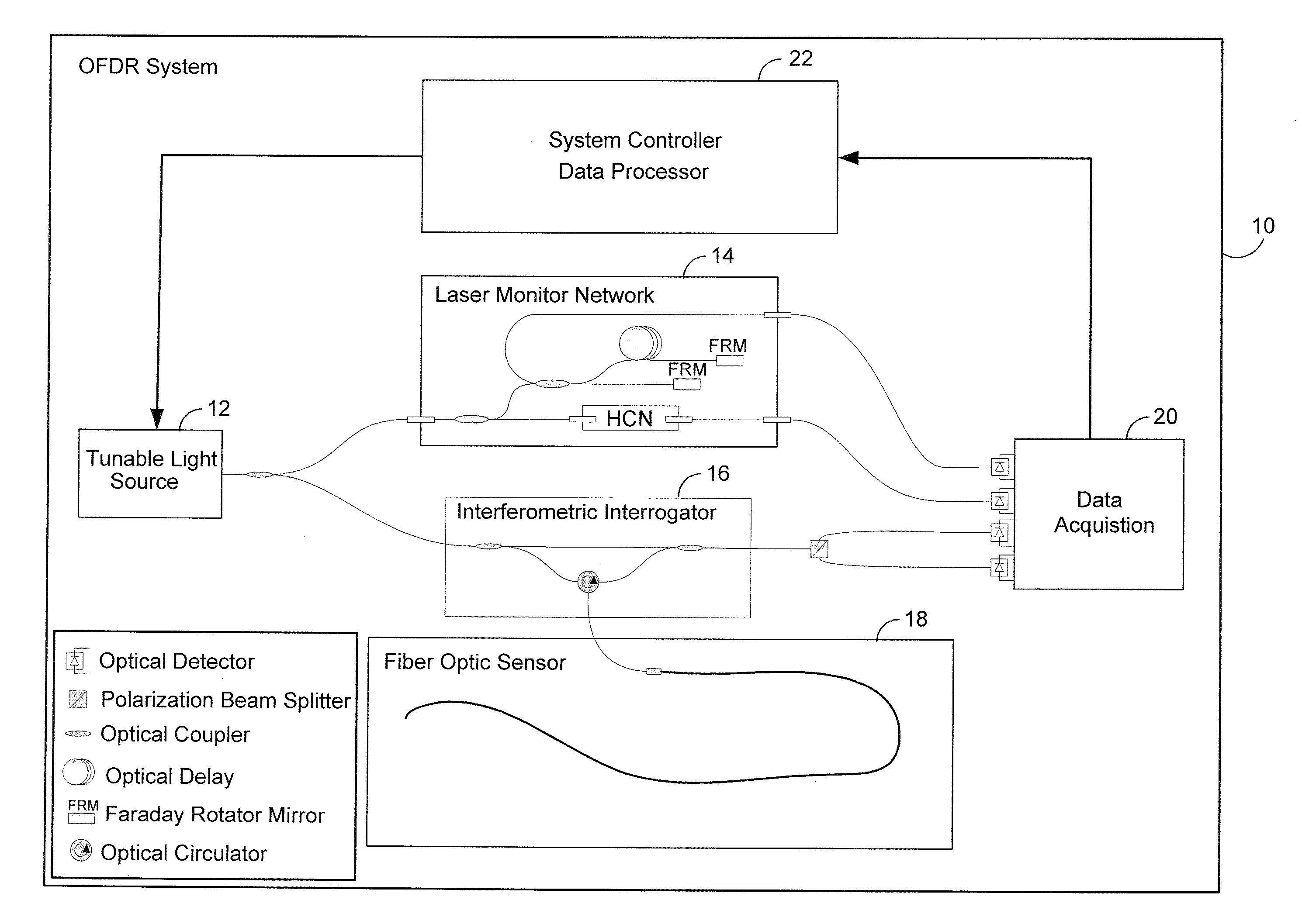
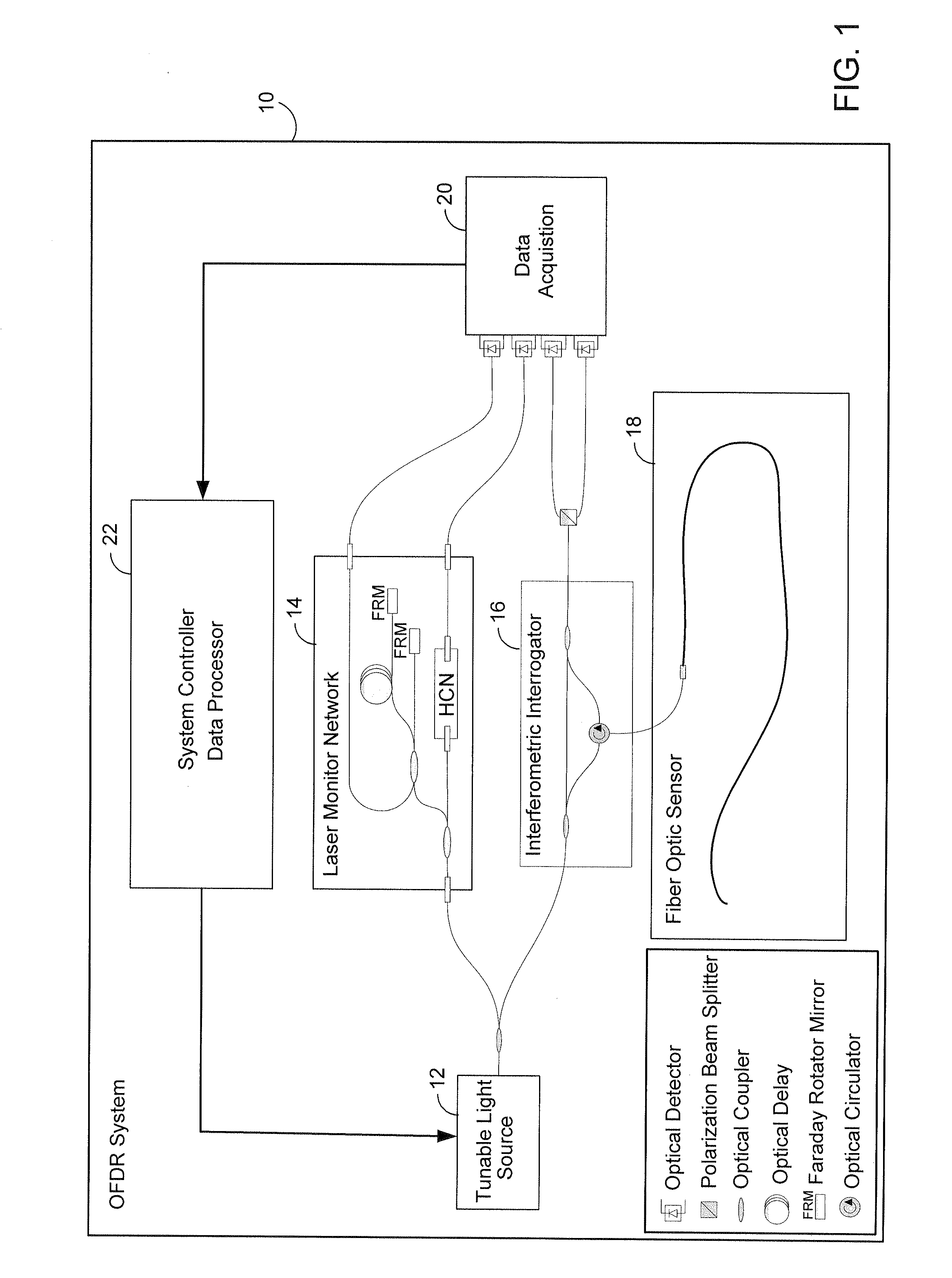
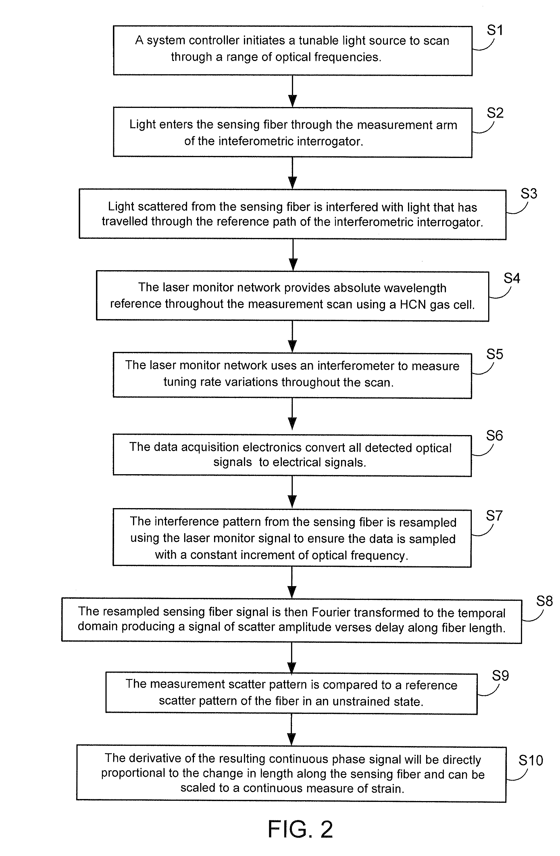
PRIORITY APPLICATION[0001]This application claims priority from U.S. provisional patent application Ser. No. 61 / 496,600, filed on Jun. 14, 2011, the contents of which are incorporated herein by reference.TECHNICAL FIELD[0002]The technology relates to multicore optical fiber that may be used for example in optical fiber applications.INTRODUCTION[0003]Optical time domain measurements with high resolution and high sensitivity are achieved through the use of Optical Frequency Domain Reflectometry (OFDR). These measurements enable technology for important fiber-optic sensing technologies, such as distributed strain sensing. Distributed strain measurements performed on a multi-core optical fiber may be used to determine the three dimensional position of the fiber as detailed in commonly-assigned, U.S. patent application Ser. No. 12 / 874,901, filed on Sep. 2, 2010, and entitled, “Optical Position and / or Shape Sensing.” A multiple channel OFDR is connected to several independent optical wave...

Claims


Application Information

Patent Timeline
Patent Type & Authority Applications(United States)
IPC IPC(8): G01L1/24
CPCG01B11/16G01B11/18G02B6/02042G02B6/02285G01L1/242G02B6/4427G02B6/441G02B6/022G02B6/4403G02B6/4405G02B6/4413
Inventor KREGER, STEPHEN T.WYSOCKI, PAUL F.LACROIX, JEFF T.
Owner INTUITIVE SURGICAL OPERATIONS INC
Why Eureka
Try Eureka