Cooling Module with Parallel Blowers

a technology of cooling module and parallel blower, which is applied in the direction of electrical apparatus casing/cabinet/drawer, casing/cabinet/drawer details, domestic cooling apparatus, etc., can solve the problems of increasing the difficulty of electronic equipment designers to provide high-power devices in relatively small packages, unacceptable noise and relatively large power consumption, and unacceptable acoustic levels. , to achieve the effect of reducing acoustic levels, enhancing cooling to electronics chassis, and increasing efficiency

Active Publication Date: 2014-04-24
LTI HLDG INC
View PDF22 Cites 33 Cited by
  • Summary
  • Abstract
  • Description
  • Claims
  • Application Information

AI Technical Summary

Benefits of technology

[0009]By means of the present invention, enhanced cooling to electronics chassis may be achieved with greater efficiency and reduced acoustic levels. The present cooling system provides cooling fluid, such as cooling air, in a generally uniform flow field across electronic components for cooling thereof. The electronic components may be disposed in a chassis, such as a telecommunication edge router, server, or a power supply unit.

Problems solved by technology

Designers of electronic equipment have become increasingly challenged to provide high-power devices in relatively small packages.
Conventional system designs often employ fans that are not well matched to the system pressures, or do not move air efficiently within the space constraints, and result in unacceptable noise and relatively large power consumption.
Relatively high aerodynamic efficiencies may be achieved with this type of air mover, but unfortunately require high rotational speeds that typically result in unacceptable acoustic levels, and assume relatively large module volumes that may not integrate well in space-constrained chassis designs.
However, centrifugal blowers have not typically been considered for electronics chassis cooling, particularly in compact arrangements, due to their relatively larger physical size.
As a result, centrifugal blowers have not commonly been considered for fit within cooling system packaging space.
For example, a single inlet centrifugal blower sized to match the performance of two axial fans in series can require twice the volumetric space, be less efficient, and result in a less uniform flow field.

Method used


Image

  • Cooling Module with Parallel Blowers
  • Cooling Module with Parallel Blowers
  • Cooling Module with Parallel Blowers

Examples


Embodiment Construction

[0024]The objects and advantages enumerated above together with other objects, features, and advances represented by the present invention will now be presented in terms of detailed embodiments described with reference to the attached drawing figures which are intended to be representative of various embodiments of the invention. Other embodiments and aspects of the invention are recognized as being within the grasp of those having ordinary skill in the art.

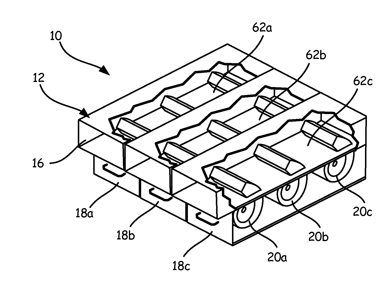
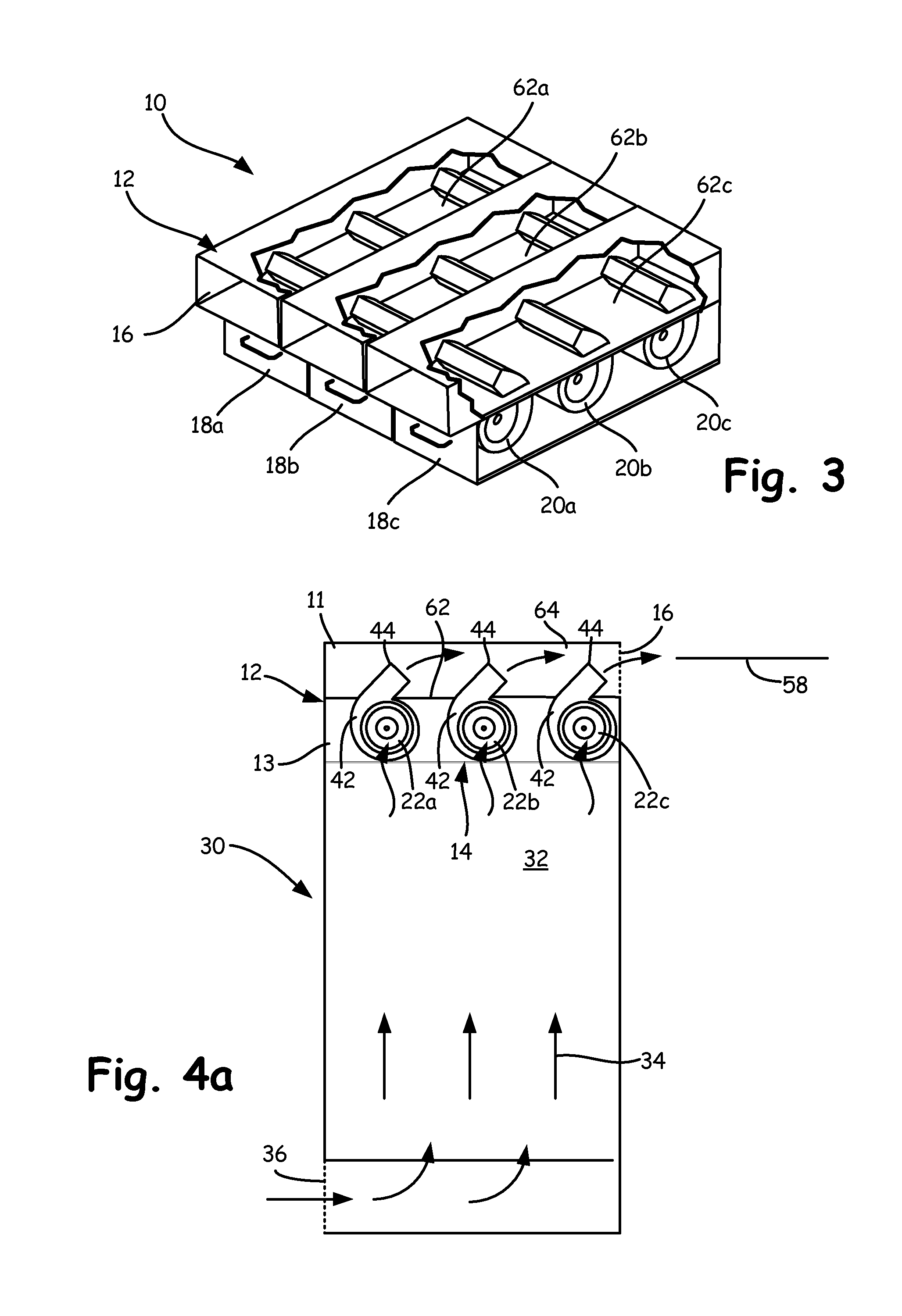
[0025]With reference now to the drawings, and first to FIGS. 3 and 4a, a cooling fan array 10 includes a frame 12 having a cooling fluid entrance 14 and a cooling fluid exit 16. Frame 12 includes a plurality of modules 18a-18c that are individually removable from and replaceable in frame 12 without operational interruption to others of modules 18a-18c. Such a characteristic is known in the art as being “hot swappable”, in that each of modules 18a-18c may be removed from frame 12 for repair or replacement without interrupting or s...


PUM


Abstract

A cooling system for an electronics chassis includes a plurality of centrifugal blowers arranged to motivate cooling air through the electronics chassis. The centrifugal blowers are arranged in one or more sets, each having blowers oriented with respective inlets in mutual facing relationship. The orientation, positioning, and alignment of the centrifugal blowers facilitates a compact arrangement of the plurality of blowers that achieves increased aerodynamic efficiencies to reduce noise output and energy consumption.

Description

CROSS-REFERENCE TO RELATED APPLICATIONS[0001]This application is a continuation in part of U.S. patent application Ser. No. 13 / 534,722, filed on Jun. 27, 2012 and entitled “Cooling Module with Parallel Blowers”, which claims priority to U.S. provisional Patent Application Ser. No. 61 / 501,535, filed on Jun. 27, 2011 and entitled “Cooling Module with Parallel Blowers”, the contents of which being incorporated herein in their entirety.FIELD OF THE INVENTION[0002]The present invention relates to cooling systems generally, and more particularly to cooling fan arrays specifically arranged for enhanced performance in motivating cooling fluid through an electronics chassis.BACKGROUND OF THE INVENTION[0003]Designers of electronic equipment have become increasingly challenged to provide high-power devices in relatively small packages. These devices require compact and highly efficient cooling systems. A typical cooling system involves moving air across one or more printed circuit boards. The ...

Claims


Application Information

Patent Timeline
Patent Type & Authority Applications(United States)
IPC IPC(8): H05K5/02
CPCH05K7/20581F24F13/02F25D17/04H05K5/06H05K7/14H05K7/20145H05K7/20736H05K7/209
Inventor DICKINSON, ROGERO'CONNOR, JOHN
Owner LTI HLDG INC
Why Eureka
Try Eureka