Electronic device including filter

a technology of electronic devices and filters, applied in the direction of impedence networks, electrical devices, transmission, etc., can solve problems such as adverse influence on receiving performan

Active Publication Date: 2014-04-24
SKYWORKS PANASONIC FILTER SOLUTIONS JAPAN
View PDF15 Cites 36 Cited by
  • Summary
  • Abstract
  • Description
  • Claims
  • Application Information

AI Technical Summary

Problems solved by technology

A part of power of the transmission signal may leak to filter 1

Method used


Image

  • Electronic device including filter
  • Electronic device including filter
  • Electronic device including filter

Examples


exemplary embodiment 1

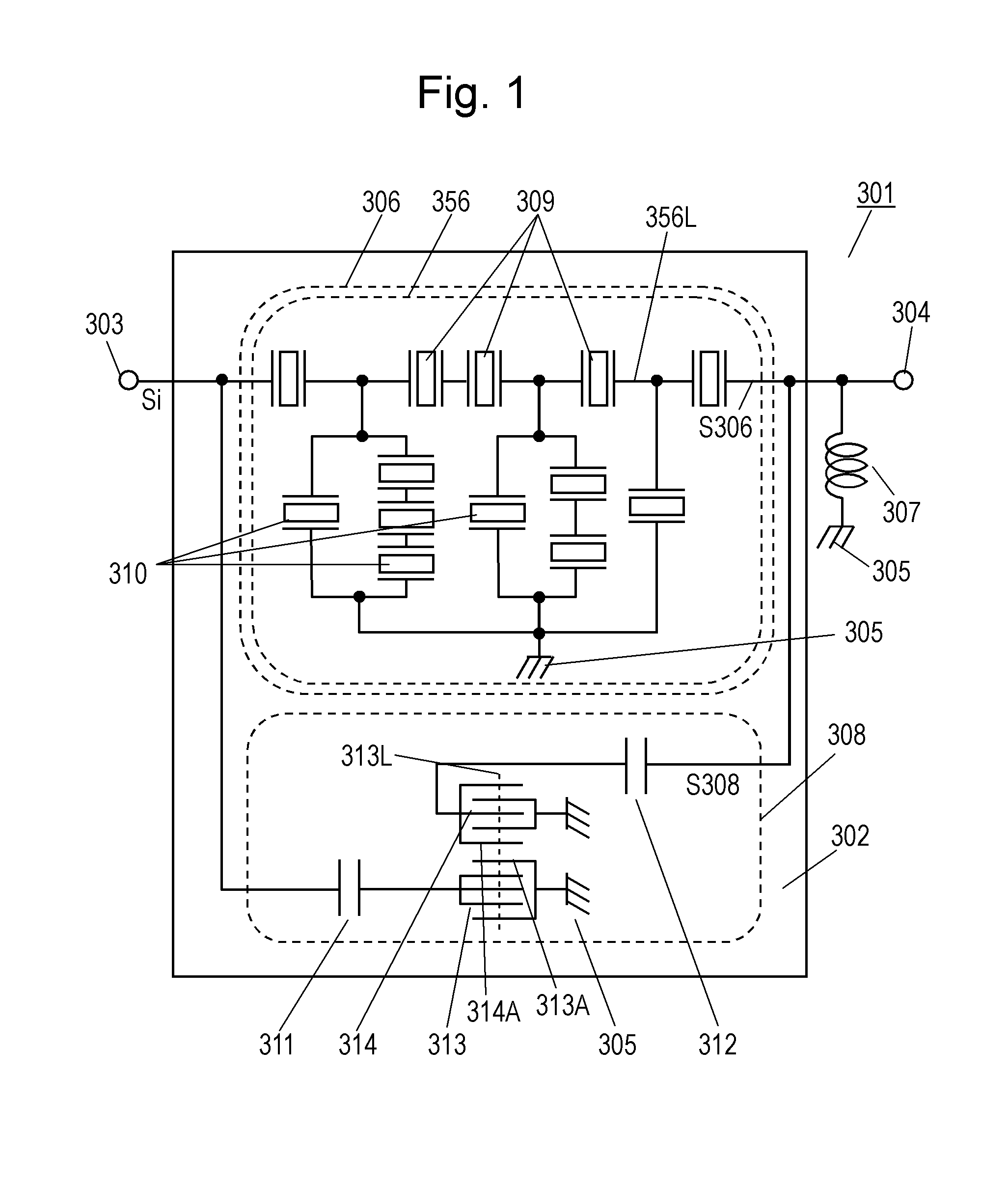
[0034]FIG. 1 is a circuit diagram of electronic device 301 according to Exemplary Embodiment 1 of the present invention. Electronic device 301 according to Embodiment 1 is a high-frequency filter. Electronic device 301 includes piezoelectric substrate 302, input terminal 303, output terminal 304, reference potential 305, main circuit 306, inductor 307, and auxiliary circuit 308.

[0035]Main circuit 306 includes filter 356 having signal line 356L connecting input terminal 303 to output terminal 304. Filter 356 includes series arm resonators 309 and parallel arm resonators 310. Series arm resonators 309 are connected in series to each other along signal line 356L between input terminal 303 and output terminal 304. Parallel arm resonators 310 are connected between signal line 356L and reference potential 305. Series arm resonators 309 and parallel arm resonators 310 are surface acoustic wave resonators formed on piezoelectric substrate 302, and constitute a ladder circuit. Filter 356 fun...

exemplary embodiment 2

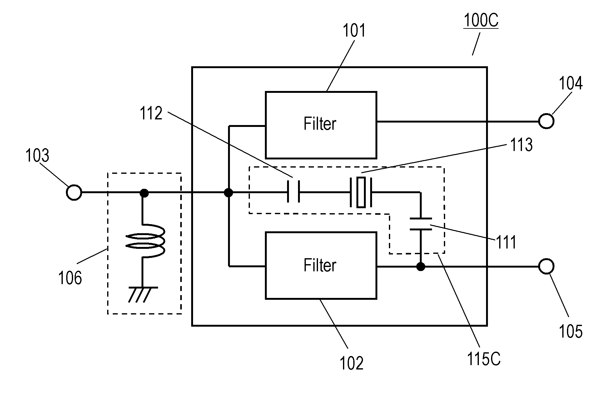
[0056]FIG. 6 is a circuit diagram of electronic device 200 according to Exemplary Embodiment 2 of the invention. Electronic device 200 represents an antenna duplexer configured to be mounted to communications apparatus 800.

[0057]Electronic device 200 includes filters 201 and 202, common terminal 203, input terminal 204, output terminal 205, phase shifter circuit 206 and piezoelectric substrate 207. Filters 201 and 202 are connected at node 209. Common terminal 203 is connected to node 209. Filter 201 is connected between node 209 and input terminal 204 while filter 202 is connected between node 209 and output terminal 205. Phase shifter circuit 206 is connected between node 209 and common terminal 203. Filters 201 and 202 constitute main circuit 208 connected from input terminal 204 to output terminal 205 via filter 201, node 209, and filter 202. Main circuit 208 further includes connection wiring 299 connecting filter 201 to filter 202 such that filter 202 is connected in series to...

exemplary embodiment 3

[0090]FIG. 14 is a circuit diagram of electronic device 410 according to Exemplary Embodiment 3 of the present invention. Electronic device 410 is a high-frequency filter used as an antenna duplexer in a radio communications apparatus. Electronic device 410 includes filters 411 and 412, common terminal 413, unbalanced input terminal 414, a pair of balanced output terminals 415A and 415B, ground 416, and inductor 417. Filter 411 and filter 412 function as a transmission filter and a reception filter of the antenna duplexer, respectively. Common terminal 413 is configured to be connected to an antenna.

[0091]Filter 411 has signal line 418 connected between common terminal 413 and input terminal 414. Filter 411 includes series arm resonators 419 connected in series to each other along signal line 418 between common terminal 413 and input terminal 414. Filter 411 further includes parallel arm resonators 420 connected between signal line 418 and ground 416. Series arm resonators 419 and p...


PUM


Abstract

An electronic device includes a main circuit connected between an input terminal and an output terminal, and an auxiliary circuit connected in parallel to the main circuit between the input terminal and the output terminal. The main circuit includes a filter having a first passband and a stopband. The auxiliary circuit has a passing characteristic that allows a signal having a frequency in a certain frequency band inside the stopband to pass through the auxiliary circuit. The main circuit is configured to output a main signal in response to an input signal. The auxiliary circuit is configured to output an auxiliary signal in response to the input signal. The main signal and the auxiliary signal contain phase components opposite to each other in the certain frequency band inside the stopband. This electronic device has an attenuation amount in the stopband.

Description

TECHNICAL FIELD[0001]The present invention relates to an electronic device including a filter for use in various telecommunications apparatuses and electronic devices.BACKGROUND ART[0002]FIG. 28 is a circuit diagram of conventional electronic device 1301, a high-frequency filter, used in an electronic device, such as a radio communications apparatus. Electronic device 1301 includes input / output terminals 1302 and 1303, signal line 1304, series arm resonators 1305, and parallel arm resonators 1306. Signal line 1304 connects between input / output terminals 1302 and 1303. Series arm resonators 1305 are connected in series to each other along signal line 1304. Parallel arm resonators 1306 are connected between signal line 1304 and reference potential 1308. Series arm resonators 1305 and parallel arm resonators 1306 constitute a ladder circuit, and function as a band-pass filter having a passband and stopbands.[0003]Conventional electronic device 1301 has a limitation in an attenuation am...

Claims


Application Information

Patent Timeline
IPC IPC(8): H04B1/40
CPCH04B1/40H03H9/725H03H9/0085H03H9/6433H03H9/6483H03H9/0028H03H9/542H03H9/6413
Inventor FUJIWARA, JOJIJIBU, TORUKOMATSU, TOMOYANAKAMURA, HIROYUKITSURUNARI, TETSUYANISHIMURA, KAZUNORI
Owner SKYWORKS PANASONIC FILTER SOLUTIONS JAPAN
Why Eureka
Try Eureka