Method for calibrating yaw rate sensors

a technology of yaw rate and sensor, which is applied in the direction of speed/acceleration/shock measurement devices, speed/acceleration/shock testing/calibration, instruments, etc., can solve the problems of time-consuming and cost-intensive calibrating methods, cross-coupling of drive oscillation and detection oscillation, etc., to achieve fast and more economical production process, high calibrating accuracy

Active Publication Date: 2014-05-01
ROBERT BOSCH GMBH
View PDF2 Cites 5 Cited by
  • Summary
  • Abstract
  • Description
  • Claims
  • Application Information

AI Technical Summary

Benefits of technology

[0007]An object of the present invention is therefore to provide a method for determining the sensitivity of a plurality of yaw rate sensors to be calibrated from individual measurements of a smaller number of yaw rate sensors referred to as sampling yaw rate sensors, which does not exhibit the disadvantages of the related art and makes it possible to calibrate a plurality of yaw rate sensors to be calibrated without causing mechanical movements of all these yaw rate sensors with a simultaneously high calibrating accuracy. This provides a significantly faster and more economical production process of the finished yaw rate sensors.
[0008]In contrast to the related art, the method according to the present invention for calibrating yaw rate sensors has the advantage that it does not have the disadvantages of the related art and makes it possible to calibrate yaw rate sensors without applying a yaw rate to all of these yaw rate sensors to be calibrated. Furthermore, it is advantageously possible to achieve an additional improvement of the calibrating accuracy compared to the related art by using a, test signal.
[0009]According to a preferred refinement, it is provided that in the first method step, the scaling function is additionally determined from a measured second sample test signal sensitivity and a measured second sample yaw rate sensitivity of a second sampling yaw rate sensor, the scaling function being determined as a function of a first and second sample drive frequency and / or sample detection frequency, and in the second method step, the production yaw rate sensitivity is calculated for the production yaw rate sensor from the measured production test signal sensitivity, a measured production drive frequency and / or a measured production detection frequency and the value of the scaling function, the scaling function being calculated as a function of the measured production drive frequency and / or the measured production detection frequency, the scaling function being interpreted as linear as a function of the production drive frequency and / or the production detection frequency. This makes it advantageously possible to achieve a higher calibrating accuracy in that the scaling function is determined as a function of an increasing number of sampling points and / or the standard measuring inaccuracy is reduced.
[0010]According to another preferred refinement, it is provided that a quadrature signal in particular is used as a test signal for determining the test signal sensitivity. This makes it advantageously possible to apply a quadrature signal to the test device, so that with the aid of a forced miscalibration, quadrature forces are generated parallel to the detection direction for compensating quadrature disturbance variables which occur due to manufacturing-related imperfections in the sensor structure during excitation of the drive oscillation and are superposed on the detection movement of the seismic mass.
[0011]According to another preferred refinement, it is provided that for measuring the first and second sample yaw rate sensitivity, the axis of rotation extends perpendicularly to the main plane of extent, and for measuring an additional first sample yaw rate sensitivity of the first sampling yaw rate sensor, an additional axis of rotation extends parallel to the main plane of extent and perpendicularly to the axis of rotation. This makes it advantageously possible to determine the sample yaw rate sensitivity pattern of yaw rate sensors having sensitivity about the axis of rotation and about the additional axis of rotation, and thus further simplify and improve the calibrating method of yaw rate sensors significantly.
[0012]According to another preferred refinement, it is provided that in the case of yaw rate sensors having sensitivity about the axis of rotation and the additional axis of rotation, in the first method step, an additional scaling function is additionally determined for the first sampling yaw rate sensor between the test signal sensitivity, the yaw rate sensitivity, an additional test signal sensitivity and an additional yaw rate sensitivity from the measured first sample test signal sensitivity and the measured first sample yaw rate sensitivity and from a measured additional first sample test signal sensitivity and a measured additional first sample yaw rate sensitivity, and in the second method step, an additional production yaw rate sensitivity is additionally calculated for the production yaw rate sensor from the calculated production yaw rate sensitivity, the additional scaling function, the measured production test signal sensitivity and a measured additional production test signal sensitivity, and the production yaw rate sensor is subsequently adjusted with the aid of the additional production yaw rate sensitivity. This makes it advantageously possible to calibrate a large number of yaw rate sensors having sensitivity about more than one axis of rotation in a particularly simple and improved manner in contrast to the related art, in particular without applying a yaw rate to the yaw rate sensors.

Problems solved by technology

Imperfections in the mechanical sensor structure may result in cross-couplings of the drive oscillation and the detection oscillation.
Process variations in the manufacturing process of yaw rate sensors may disadvantageously result in a variation of the sensitivity of the yaw rate sensors.
Special devices are needed for this purpose, which is disadvantageously associated with a very time-intensive and cost-intensive calibrating method.
Compared to a calibrating method in which a yaw rate is applied to yaw rate sensors, this method disadvantageously results in a lower calibrating accuracy.

Method used


Image

  • Method for calibrating yaw rate sensors
  • Method for calibrating yaw rate sensors
  • Method for calibrating yaw rate sensors

Examples


Embodiment Construction

[0016]Identical components are consistently provided with the same reference numerals in the various drawings and are therefore named or mentioned only once.

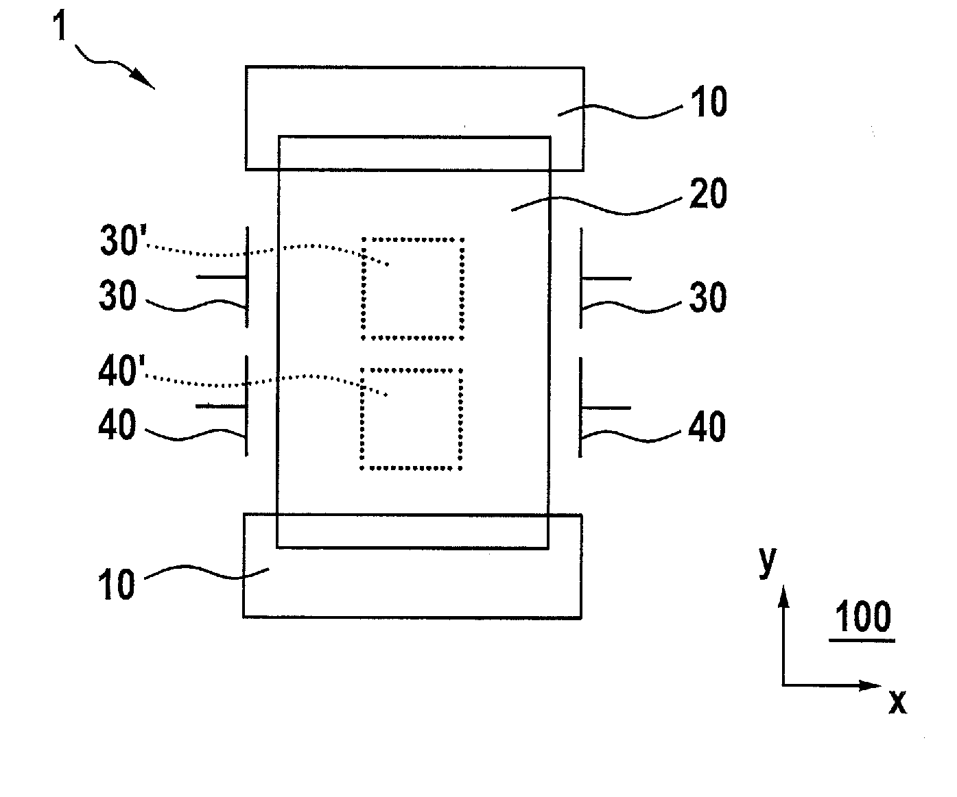
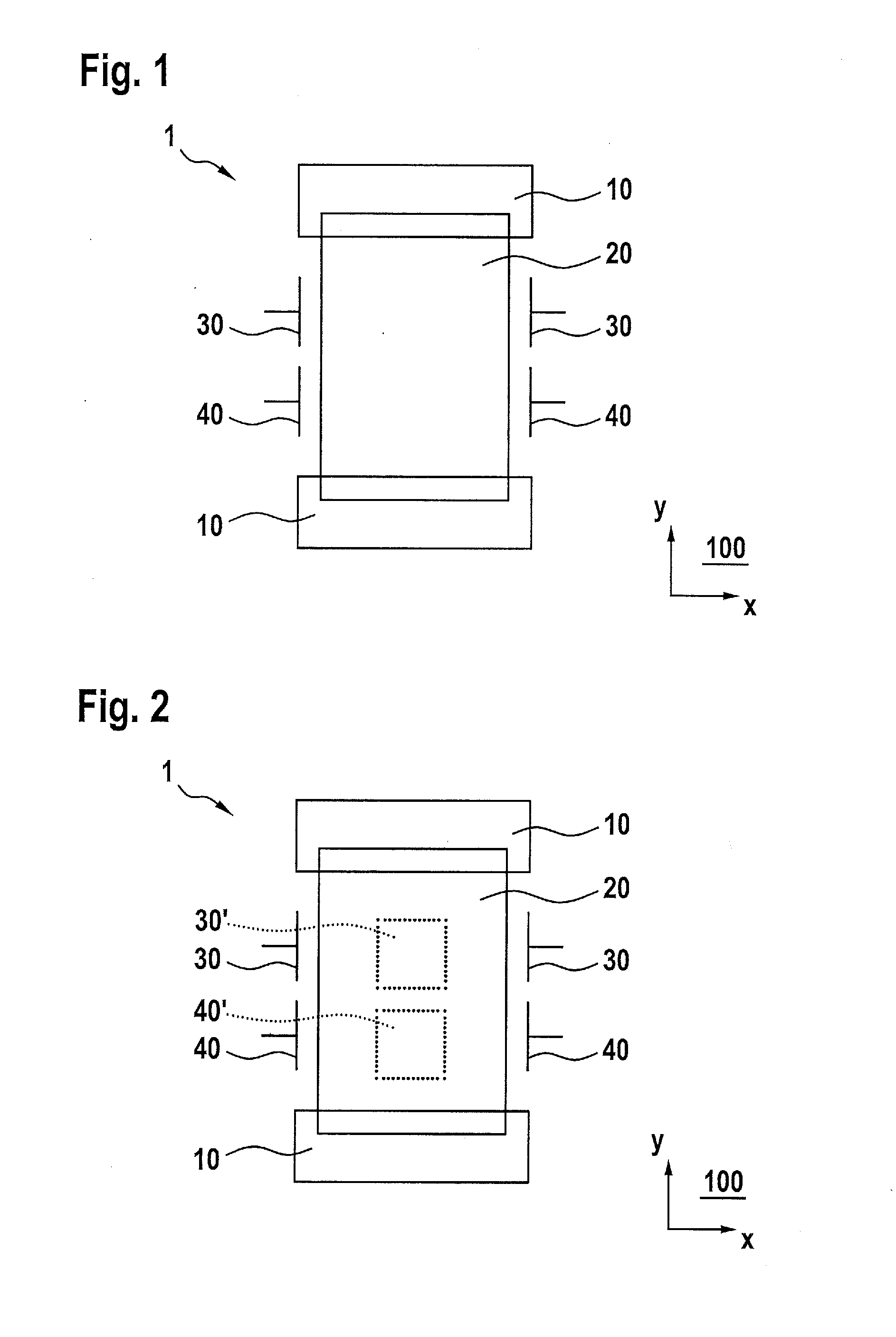
[0017]FIG. 1 shows a schematic diagram of an exemplary specific embodiment of yaw rate sensor 1 according to the present invention. A substrate, which is not shown, has a main plane of extent 100. Yaw rate sensor 1 includes a drive device 10, which is provided for the capacitive vibrational excitation of a seismic mass 20 which is movable in relation to the substrate in the Y direction (drive direction). If a yaw rate about an axis of rotation extending perpendicularly to main plan of extent 100 is applied to yaw rate sensor 1, the Coriolis force causes a force action on the seismic mass in a detection direction parallel to the X-direction. In a so-called open-loop system, the seismic mass is deflected due to the Coriolis force, while in a so-called closed-loop system, the force action is compensated with the aid of an electrost...


PUM


Abstract

A method for calibrating a selected yaw rate sensor includes: determining a scaling function between a yaw rate sensitivity and a test signal sensitivity of a yaw rate sensor selected for carrying out a test and denoted as first sampling yaw rate sensor is determined in a first method step, the scaling function being determined from a measured first sample yaw rate sensitivity and from a measured first sample test signal sensitivity of the sampling yaw rate sensor; calculating a production yaw rate sensitivity for a yaw rate sensor denoted as production yaw rate sensor from a measured production test signal sensitivity of the production yaw rate sensor and the scaling function; and subsequently calibrating the production yaw rate sensor with the aid of the production yaw rate sensitivity.

Description

BACKGROUND OF THE INVENTION[0001]1. Field of the Invention[0002]The present invention relates to a method for calibrating yaw rate sensors.[0003]2. Description of the Related Art[0004]Such methods for calibrating yaw rate sensors are generally known. The measuring principle for yaw rate sensors is the use of the Coriolis effect. For that purpose, a seismic mass of the sensor structure is put into a drive oscillation in a drive direction. In the case of an external yaw rate occurring perpendicularly to the direction of the drive oscillation, Coriolis forces occur which cause a detection oscillation into a detection direction of the seismic mass. Imperfections in the mechanical sensor structure may result in cross-couplings of the drive oscillation and the detection oscillation. The cause of this cross-coupling is displacement proportional and is denoted as quadrature.[0005]Process variations in the manufacturing process of yaw rate sensors may disadvantageously result in a variation ...

Claims


Application Information

Patent Timeline
Patent Type & Authority Applications(United States)
IPC IPC(8): G01P21/00
CPCG01P21/00G01C19/5755G01C25/005
Inventor FRANKE, AXELHATTASS, MIRKO
Owner ROBERT BOSCH GMBH
Why Eureka
Try Eureka