
Portable tool

a technology of portable tools and switch units, which is applied in the field of portable tools, can solve the problems of increasing the size of portable tools, increasing the manufacturing cost of portable tools, and increasing the number of component parts, so as to improve the operability of the operation switch unit, facilitate the operation and reduce the size of the operation display panel

Active Publication Date: 2014-05-01
HITACHI KOKI CO LTD
View PDF23 Cites 27 Cited by
  • Summary
  • Abstract
  • Description
  • Claims
  • Application Information

AI Technical Summary

Benefits of technology

The present invention provides a portable tool with a small operation display panel that includes a driving information display unit and an operation switch unit. The driving information display unit shows multiple pieces of driving information, and a specific piece of driving information can be selected by using the operation switch unit. The reduced size of the operation display panel makes it easier to operate and improves the visibility of the driving information display unit.

Problems solved by technology

If the operation display panel unit is enlarged, a worker is required to select and operate a specific switch from among a plurality of switches provided on a large operation panel unit for displaying a specific function, and a problem in operability arises.
Further, since a control board on which the large operation display panel unit is attached also has to be enlarged, the number of component parts is increased, so that the portable tool is enlarged in size and the manufacturing cost thereof is increased.

Method used


Image

  • Portable tool
  • Portable tool
  • Portable tool

Examples


Embodiment Construction

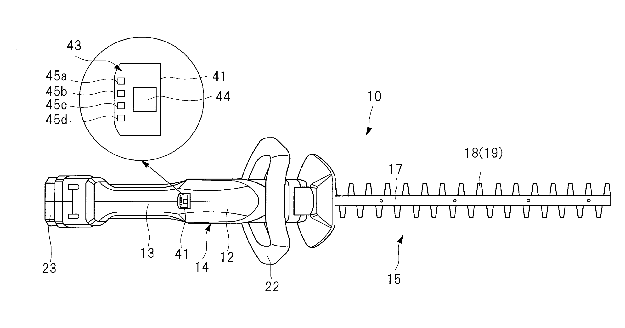
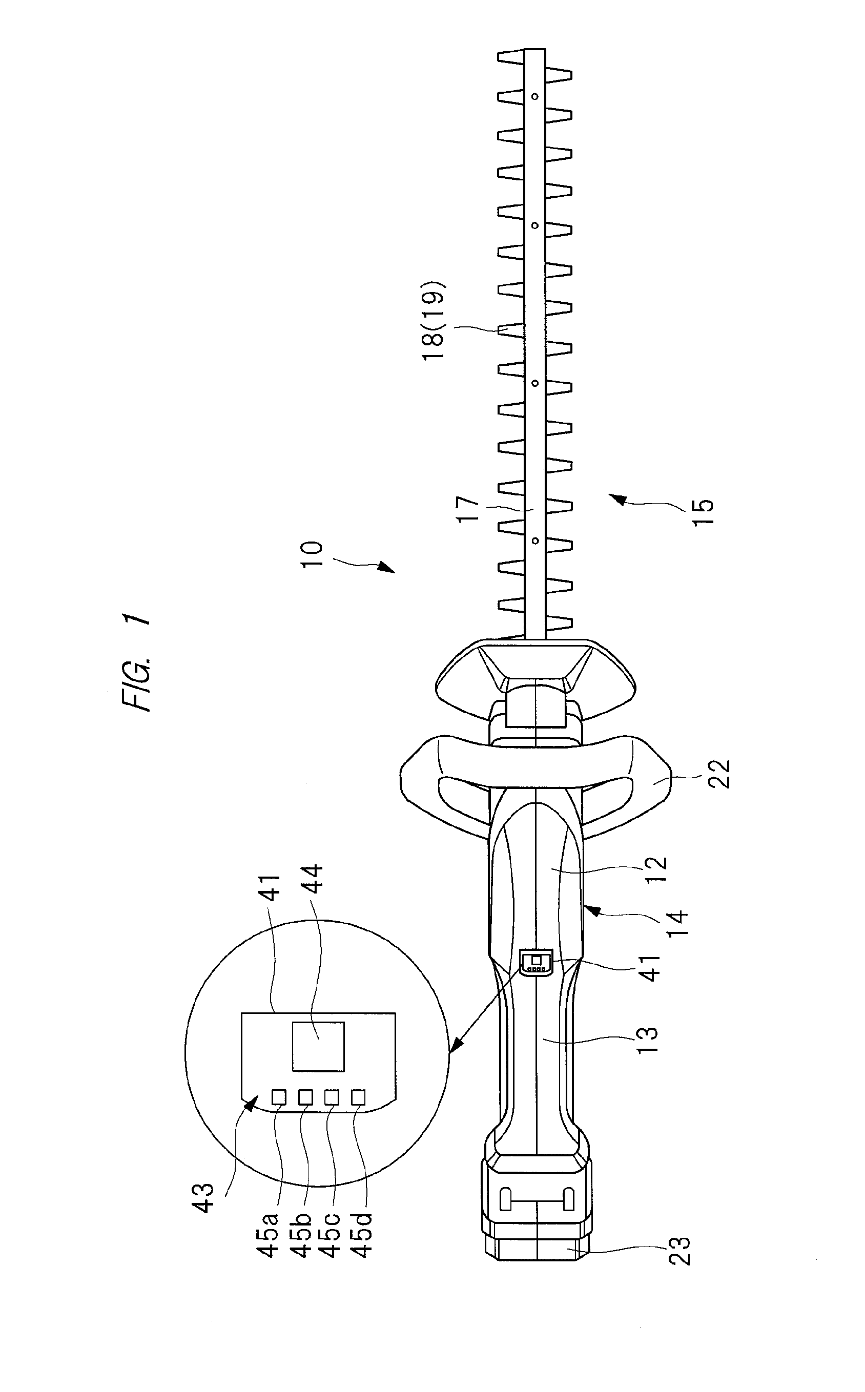
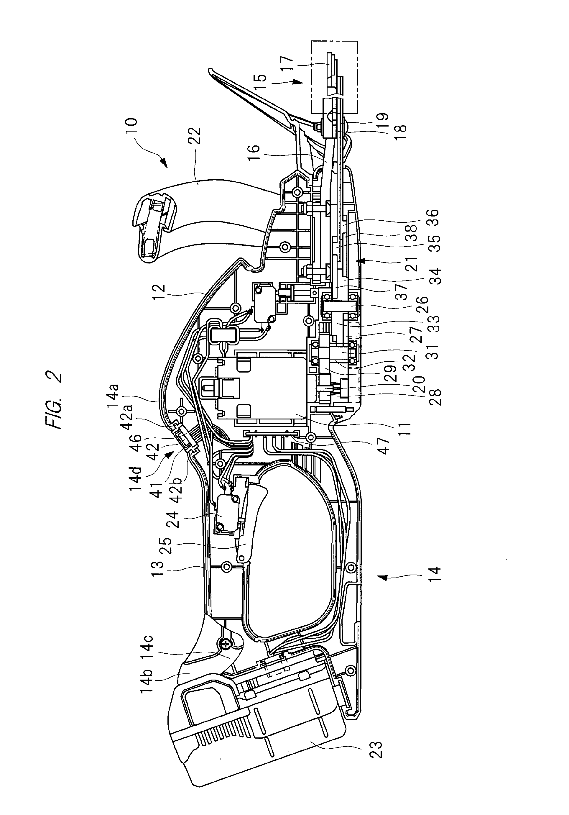
[0020]Hereinafter, an embodiment of the present invention will be described in detail with reference to the drawings. FIG. 1 and FIG. 2 show a hedge clipper serving as an example of a portable tool, that is, a hedge trimmer. The hedge clipper 10 has a portable-tool main body, that is, a casing 14 integrally made up of a power source housing 12 in which an electric motor 11 serving as a power source is housed and a main handle 13, and the casing 14 has the power source housing 12 and the main handle 13 on a rear side thereof. On a front end part of the casing 14, a blade assembly 15 as a tip tool is provided, and the blade assembly 15 projects forward from the front end part of the casing 14.

[0021]The blade assembly 15 has a guide bar 17 fixed to the casing 14 with a bracket 16. Two trimming blades each formed of a rod-like plate, that is, blades 18 and 19 are attached to the guide bar 17 so as to be reciprocated in a longitudinal direction. Rotational motion of an output shaft 20 of...


PUM


Abstract

A casing of a hedge clipper which is a portable tool is provided with a power source housing in which an electric motor is housed and a main handle held by a worker, and blades serving as a tip tool are provided to the casing. An operation display panel is provided on the main handle, and a driving information display unit which displays a battery remaining capacity and a rotation speed of an electric motor as a plurality of pieces of driving information is provided on the operation display panel. The selection of the information to be displayed is switched by the operation of an operation switch unit provided in the operation display panel.

Description

CROSS-REFERENCE TO RELATED APPLICATION[0001]The present application claims priority from Japanese Patent Application No. 2012-239785 filed on Oct. 31, 2012, the content of which is hereby incorporated by reference into this application.TECHNICAL FIELD OF THE INVENTION[0002]The present invention relates to a portable tool provided with an operation display device which displays driving information of a portable tool in which a tip tool is driven by a driving source such as an electric motor like a hedge clipper or others.BACKGROUND OF THE INVENTION[0003]A portable tool in which a tip tool is driven by a power source such as an electric motor includes a hedge clipper, a round saw, a driver, an impact driver, a hammer, a hammer drill, a jigsaw, a grinder, a blower and others. The hedge clipper has a pair of blades as a tip tool and is used for pruning the branches and leaves of shrubs and trees, and it is also referred to as a hedge trimmer. The round saw has a disk saw blade as a tip ...

Claims


Application Information

Patent Timeline
IPC IPC(8): B25F5/02
CPCB25F5/02A01G3/053B24B23/005B25F5/00B26B21/4056A01G3/06B25F5/001H01H9/06
Inventor IWATA, KAZUTAKASHIMIZU, YASUTAKASHIBATA, SHOGO
Owner HITACHI KOKI CO LTD
Learn More