

Electronic component
- Summary
- Abstract
- Description
- Claims
- Application Information
AI Technical Summary
Benefits of technology
Problems solved by technology
Method used
Image

Examples
Embodiment Construction
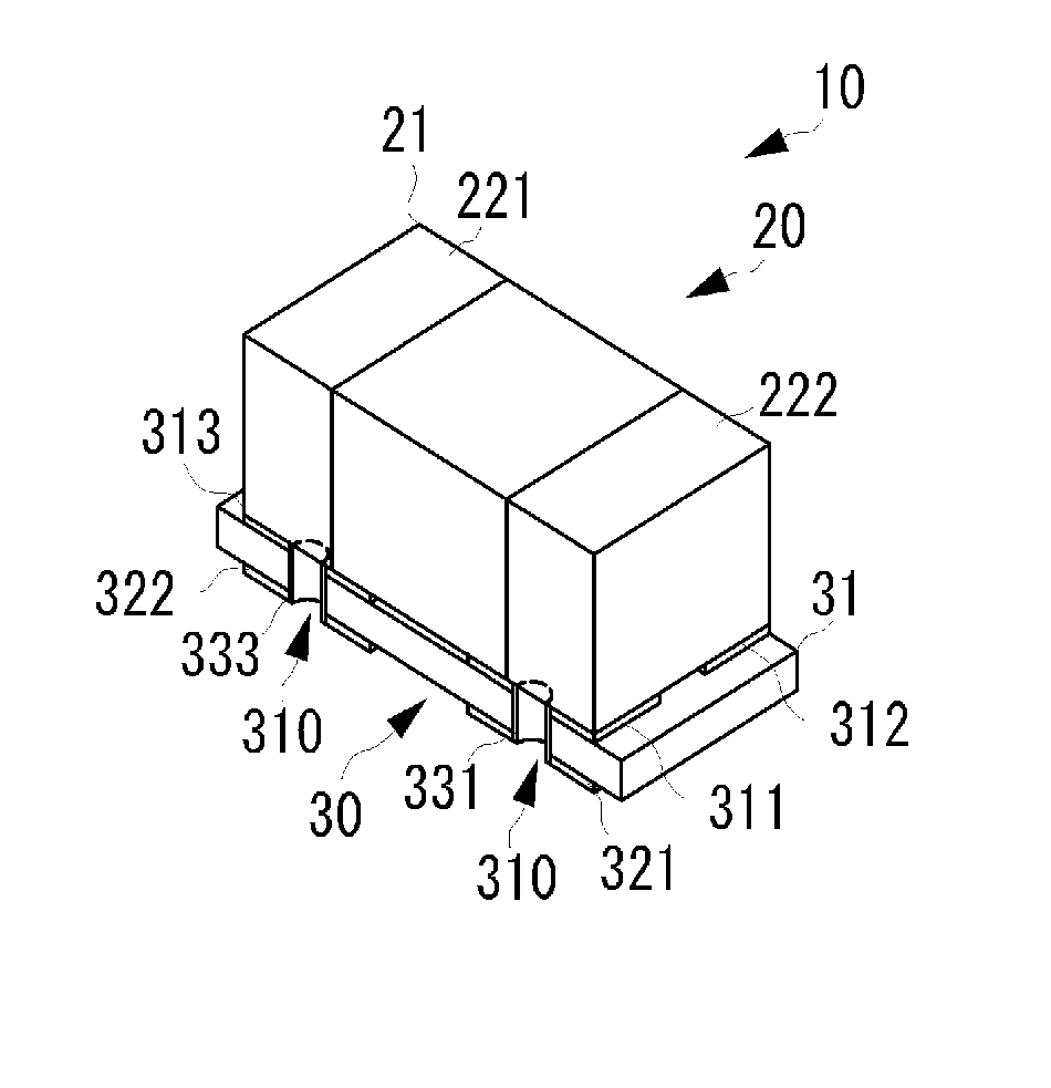
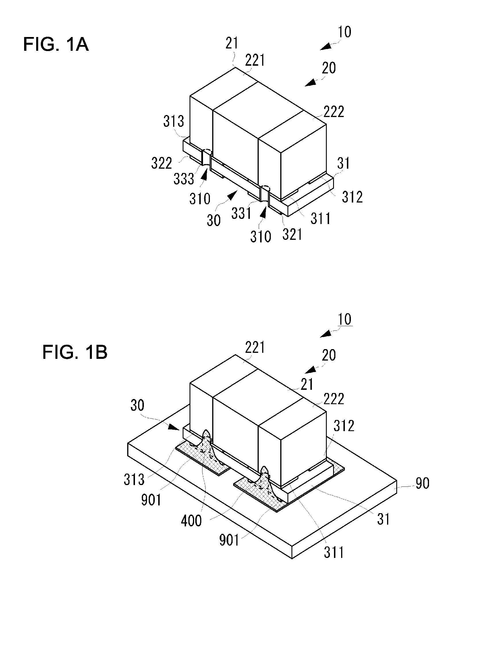
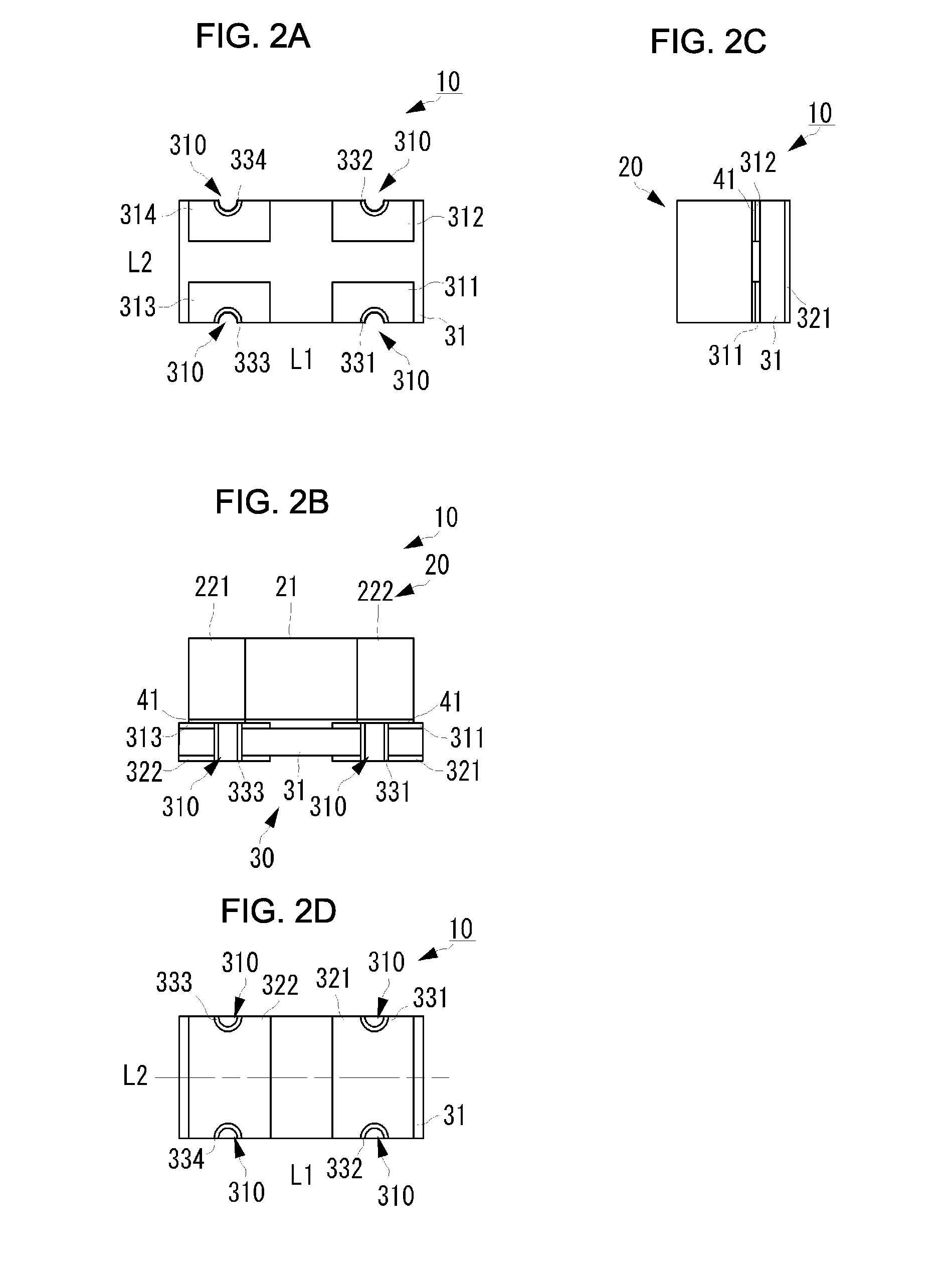
[0025]An electronic component according to a preferred embodiment of the present invention will be described with reference to the drawings. FIG. 1A is a perspective view of the outward appearance of an electronic component 10 according to a preferred embodiment of the present invention. FIG. 1B is a perspective view of the mounting state of the electronic component 10. FIGS. 2A-2D are four-side views of the electronic component 10 according to the present preferred embodiment, of which FIG. 2A is a plan view, FIG. 2B is a first (longitudinal) side view, FIG. 2C is a second (lateral) side view, and FIG. 2D is a rear view. FIGS. 3A and 3B are a first side view and a second side view each illustrating the mounting state of the electronic component 10 according to the present preferred embodiment.
[0026]The electronic component 10 includes a multilayer ceramic capacitor (chip component) 20 and an interposer 30. In FIG. 2A, the multilayer ceramic capacitor 20 that is mounted on the subst...
PUM
 Abstract
Description
Claims
Application Information